Description of the terminals, Connecting the power supply module – CIRCUTOR QNA500 series User Manual
Page 14
POWER QUALITY ANALYZER QNA500 8IO
QNA500 8IO Instruction manual
14 / 111
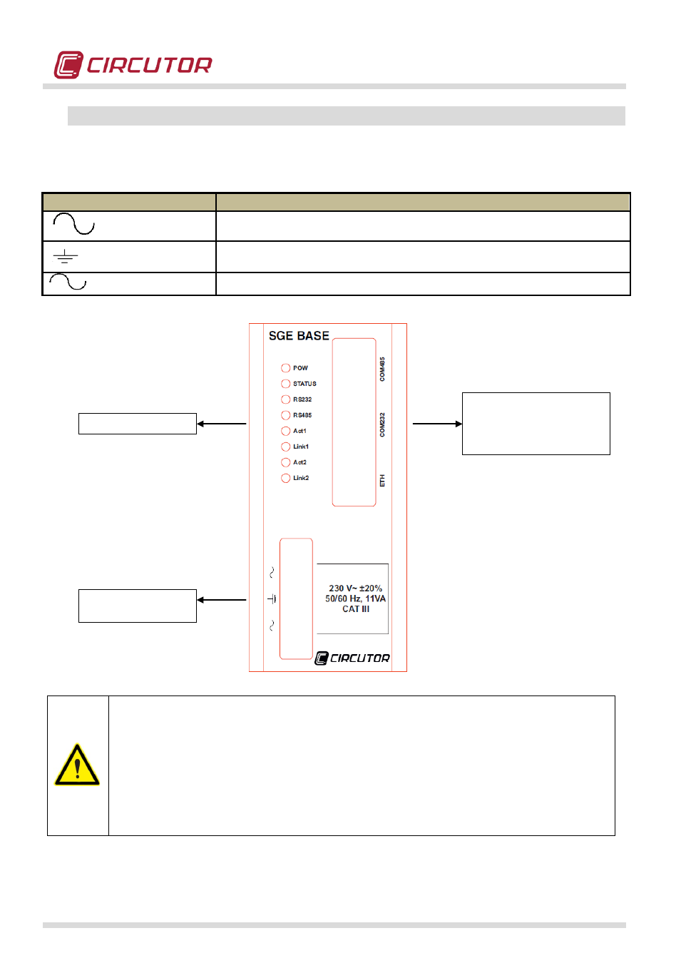
5.5.- DESCRIPTION OF THE TERMINALS
5.5.1.- CONNECTING THE POWER SUPPLY MODULE
The equipment must be connected to a power circuit protected with gl-type
fuses, in compliance with IEC 269, or M-type, with values from 0.5 to 1 A / 600
V (UL listed). It must be fitted with a circuit-breaker switch or equivalent
device, in order to be able to disconnect the device from the power supply.
The power circuit and voltage measurement circuits are connected with a
cable with a minimum cross-section of 1 mm
2
. (AWG 17). The current
transformer's secondary connection line must have a minimum cross-section
of 2 mm
2
. (AWG 14 Cu) and withstand a minimum of 60ºC.
TERMINAL
DESCRIPTION
Power supply connection
Ground connection
Power supply connection
Indicator LED
Communications ports
RS-485
RS-232
ETHERNET
Auxiliary power
supply