Communication connection diagram, Rs-232 – CIRCUTOR QNA500 series User Manual
Page 17
POWER QUALITY ANALYZER QNA500 8IO
QNA500 8IO Instruction manual
17 / 111
5.6.- COMMUNICATION CONNECTION DIAGRAM
M-BASE has 3 built-in communications ports that can send the information from the connected
modules to external devices. The ports are as follows:
• RS-232
• RS-485
• ETHERNET (TCP/IP)
The 3 communications ports operate as independent systems. In other words, they can simultaneously
request information from all connected modules.
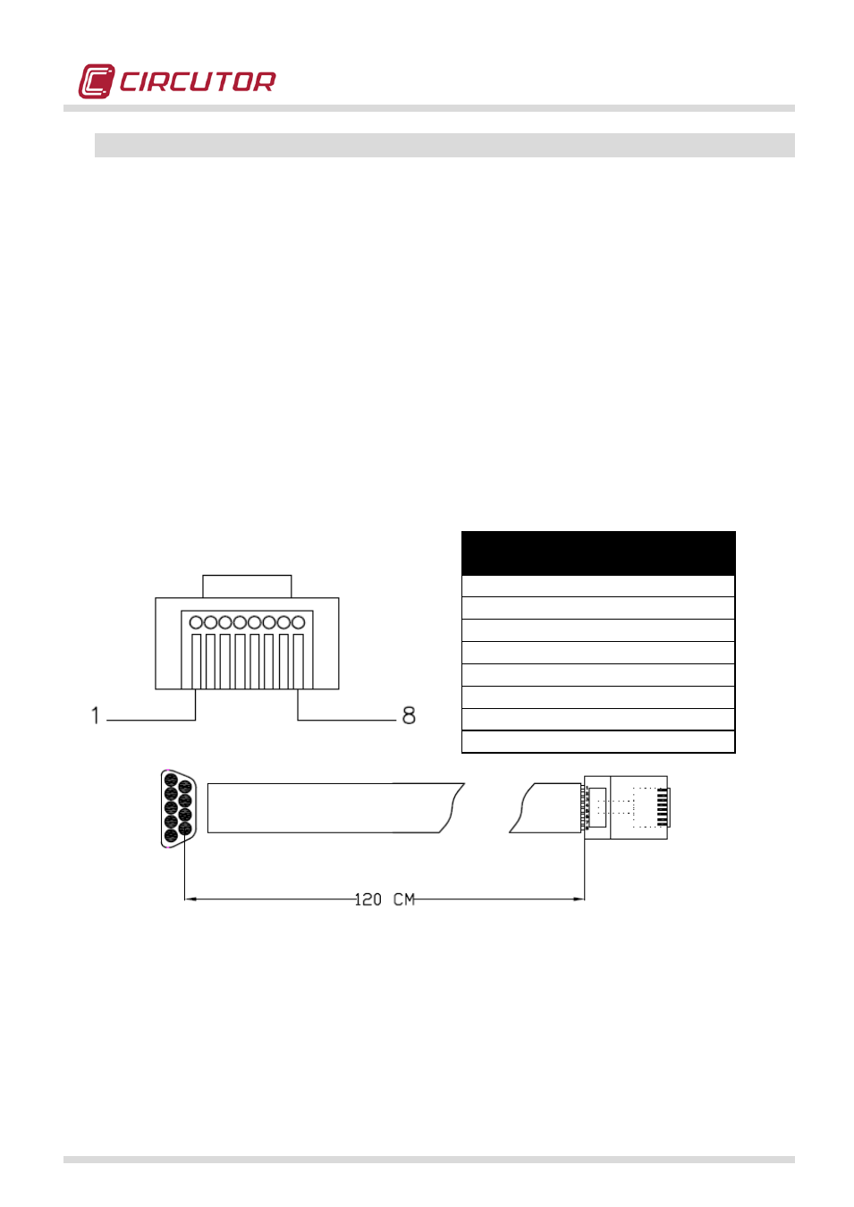
5.6.1.- RS-232
QNA 500 system is supplied with an RS-232 communications cable. The cable wiring diagram is as
follows:
The RS-232 communications port can be used to access the different modules connected to the M-
BASE module. Each module has a peripheral number (default: M-BASE = 01, M-QNA500= 02 and M-
8IO = 10, M-8IOR=10), which must be taken into account when establishing communications.
FRONT VIEW
(RJ45)
DB-9 CONNECTOR
1 (Tx)
2 (Rx)
2 (Rx)
3 (Tx)
3 (CTS)
8 (DSR)
4 (GND)
5 (GND)
5 (GND)
5 (GND)
6
-
7
-
8
-