Cvm-c10 instruction manual, Power supply v, Nl1 l2 l3 – CIRCUTOR CVM-C10 Series User Manual
Page 16
Advertising
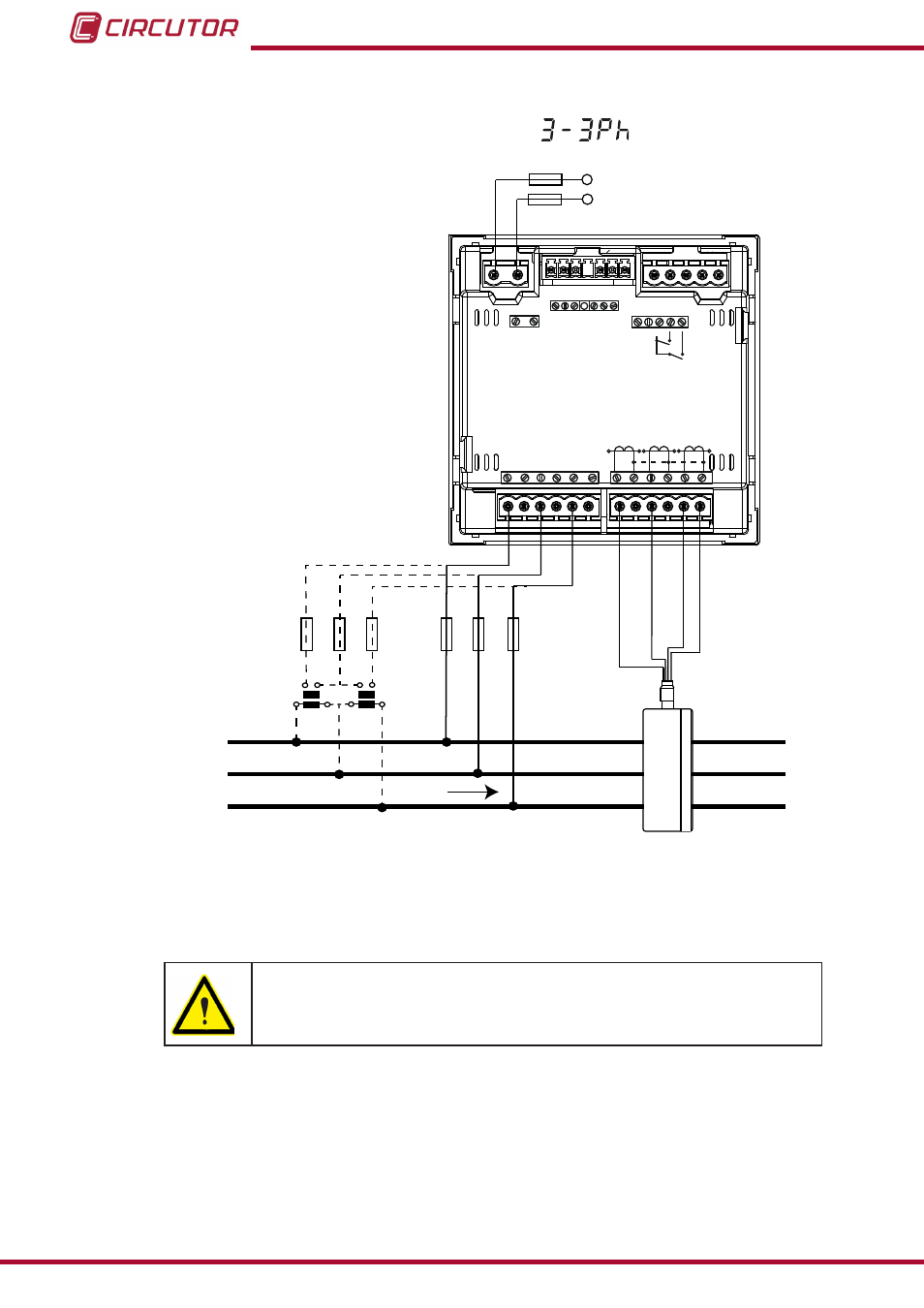
3�4�5�- Measuring Three-Phase Networks with a 3-wire connection, CVM-C10-MC model�
Measurement system:
Power
Supply
V
L1
V
L2
V
L3
N
L1
L2
L3
POWER SUPPLY
INPUTS
A
(+) B(-)
GND
RS485
S1
S2
S1
S2 S1
S2
L1
P1
P2
L2
L3
300V ~
Ph-N
Ph-Ph
520V ~
N
V
L3
L2
V
L1
V
P1
P2 P1
P2
I1 I2
OUTPUTS
Rc R2 R1
Tc T2 T1
S0- S0+ S0+
V
L1
V
L2
V
L3
a
b
A
B
a
b
A
B
3P1
2P1
1P1
3P2
2P2
1P2
Br
own/Gr
een
Gr
ey/P
ink
Gr
een/W
hit
e
Red/Blue
LOAD
Figure 7: Three-Phase measuring with a 3-wire connection, CVM-C10-MC model�
The MC transformer secondary value is set to 0.250 A (fixed value)
16
CVM-C10
Instruction Manual
Advertising