Ivie iFlex 2400 Series User Manual
Page 6
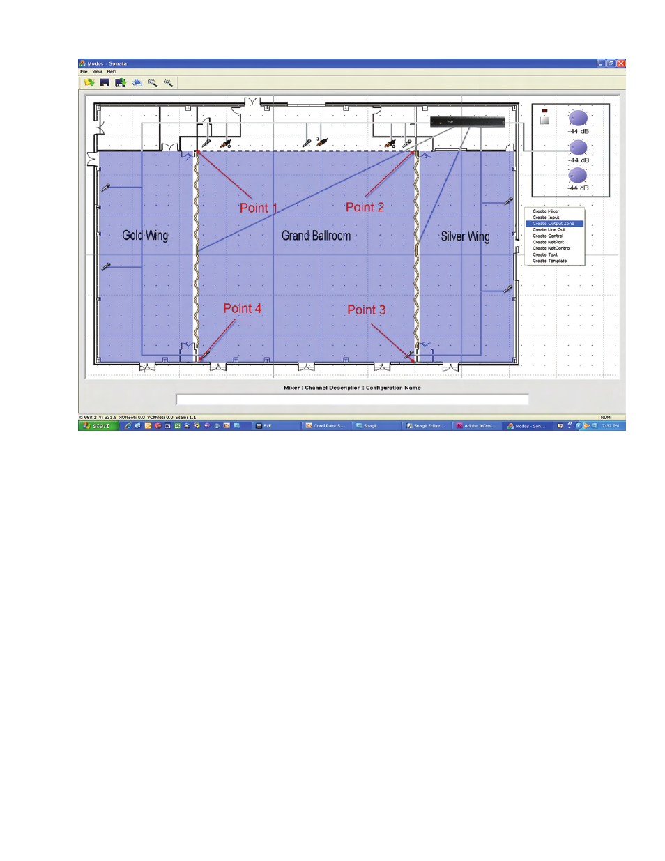
Figure 4
Output Zones
Output zones are the typical speaker zones in a
design, and are an integral part of how Sonata
TM
helps the user visualize both the system and it’s
logic. To create an output zone, right-click in
the layout area and select ‘Create Output Zone’.
Much like the polylines used to connect inputs to
the mixer, output zones are created by clicking
at multiple points. After the final point is placed,
right-click to exit zone definition.
When multiple points are selected, a shaded area
will form to show the user an area affected by the
zone. The shading is initially blue, but as logic is
input into the system, the colors of these zones will
change depending on the switch logic. This helps
the designer to simulate the system changes, such
as doors opening, switches being activated, etc..
In the example of figure 4, three zones are created.
One will cover the footprint of the grand ballroom,
and two more will handle the side wings. The
doors are placed between the wings as they show
up on the design plans, and we will later use the
simulation mode to show the doors opening and
closing, with the changes in zone colors following
the changing door states. ( Make sure to connect
the output zones to the mixer at this time)
Some cleanup items:
You can right-click on any of the inputs, outputs,
template controls, or output zones and give them
names that are more useful than their defaults.
This will be very helpful in the following steps as-
sociated with inputing the system logic.
You can create and place text objects such as
the labeling of the ballrooms in figure 4 above.
Simply right-click, and select ‘Create Text’. To
change fonts, simply right-click on the text.