Rear view, Warning important important – KLING & FREITAG K&F ACCESS T9 User Manual
Page 24
User’s Manual
ACCESS SYSTEM
KLING & FREITAG GMBH ©1995-2009
Version 6.0, 17.03.2009
Page 24 of 60
8
9
10
11
12
13
15
14
I
N
P
U
T
LINK
3
1
2
2
1
3
O
U
T
U
HIGH
T
P
L
I
T
F
3
1
2
MID
BASS
2
3
1
2
1
3
LINK
S
E
N
S
E
BASS
HIGH + MID
Made in
READ MANUAL BEFORE USE
50-60Hz / 30VA
115 / 230VAC
T 500 / T 315mA
CONTROLLER K&F ACCESS C5/9
SEND (+15 V)
POWER SEQUENCE
Fuse 115 / 230V:
Power Requirements:
Serial Number:
Germany
KLING
&
FREITAG GmbH
2
3
0
115
SELECTOR
VOLTAGE
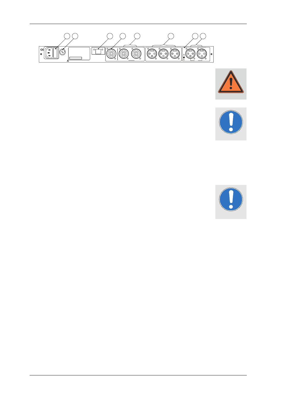
8)
FUSE
Fuse holder which is fitted with a 315mA medium slow glass fuse for 230V opera-
tions. With 115V operations, a 500mA medium slow glass fuse must be used. Never
use a fuse with specificaations different than the aforementioned values. Never by-
pass the fuse holder. The system controller can be irreparably ruined and/or even
cause a fire.
9)
VOLTAGE SELECTOR
This switch is used to adjust the equipment to the desired operational voltage level
of 115 or 230 VAC. CAUTION: the equipment can be destroyed if the wrong oper-
ating voltage level is selected!
10)
SEQUENCE SEND
About 1 second after switching on the ACCESS Controller, a control voltage of
+15V is present at both connector pins. If, for example, you have fitted your amp
rack with power amplifiers that have a remote switching feature, then connect this
output with the SEQUENCE RCV input of the first amplifier, the SEQUENCE SND
output of the first amplifier with the SEQUENCE RCV input of the second amplifier,
etc. When turning on the ACCESS Controller, all amplifiers will then be turned on
time-delayed.
11)
SENSE BASS
The amplified output signal of the bass amplifier is connected to the pins 1- and 1+
of this Speakon 4-pin connector. This signal provides the controller with information
for the bass-limiter. The ACCESS System also works without the connection from
the bass amplifier to the Sense Bass, but in this case, there is no guarantee for op-
timal operating safety. Make sure that the Speakon connector clicks into place
properly. All SENSE inputs are galvanically insulated from the amplifier with bal-
anced transformers.
12)
SENSE HIGH + MID und LINK
The amplified output signal of the mid-range and high amplifier is connected to
one of the two Speakon connectors. Here is where the ACCESS C5/9 Controller re-
ceives and evaluates the signals. It is extremely important to ensure that the polarity
is correct. The pin diagram for this is in the chapter for ‘‘Pin Diagrams of Connectors
and internal Wiring’’. The ACCESS System is connected to the respective Speakon
connector. The two connectors are connected in parallel.
13)
OUTPUT - BASS, MID und HIGH
The electronically balanced BASS, MID and HIGH line level outputs are connected to
the inputs of the corresponding amplifier. We recommend using only high-quality
connecting cables from KLING & FREITAG. Bipolar shielded microphone cable with
high-quality connectors should be used to connect the power amplifiers. Connect-
ing instructions are in the chapter for ‘‘Pin Diagrams of Connectors and internal
Wiring’’.
14)
GROUND LIFT
If the Ground Lift switch is set on LIFT, then pin 1 of the INPUT connector is not
connected to the ACCESS C5/9 Controller. There is always a connection between
the INPUT (XLR male) and the LINK (XLR female) connector. If the C5/9 is operated
with a K&F Connector Panel, then this switch must be set to GROUND.
15)
INPUT und INPUT-LINK
The C5/9 Controller is equipped with a transformer balanced input. Use the XLR-
female connectors (INPUT) as input. The parallel connected XLR-male connector is
used to link the signal to additional ACCESS controllers or amplifiers.
Rear View
Warning
Important
Important