Rear, Warning important important – KLING & FREITAG K&F ACCESS T9 User Manual
Page 28
User’s Manual
ACCESS SYSTEM
KLING & FREITAG GMBH ©1995-2009
Version 6.0, 17.03.2009
Page 28 of 60
If the cones are moved (i.e. from air movement of other sound sources), the
speakers produce voltage which may cause the LEDs to light up.
c)
The SYM: ERROR-LED indicates that there is a voltage difference of at least 5V be-
tween BASS A and BASS B. This LED also lights up if there is a phase error, in other
words, the phase between BASS A and BASS B is shifted by 180°. If this LED is lit
up, it is necessary to check the power amplifiers and the wiring.
7)
POWER ON
The POWER ON LED indicates that the system controller is on and operational. If the LED
does not light up after the equipment has been turned on, check the power supply or, if
necessary, replace the main fuse on the rear panel of the controller.
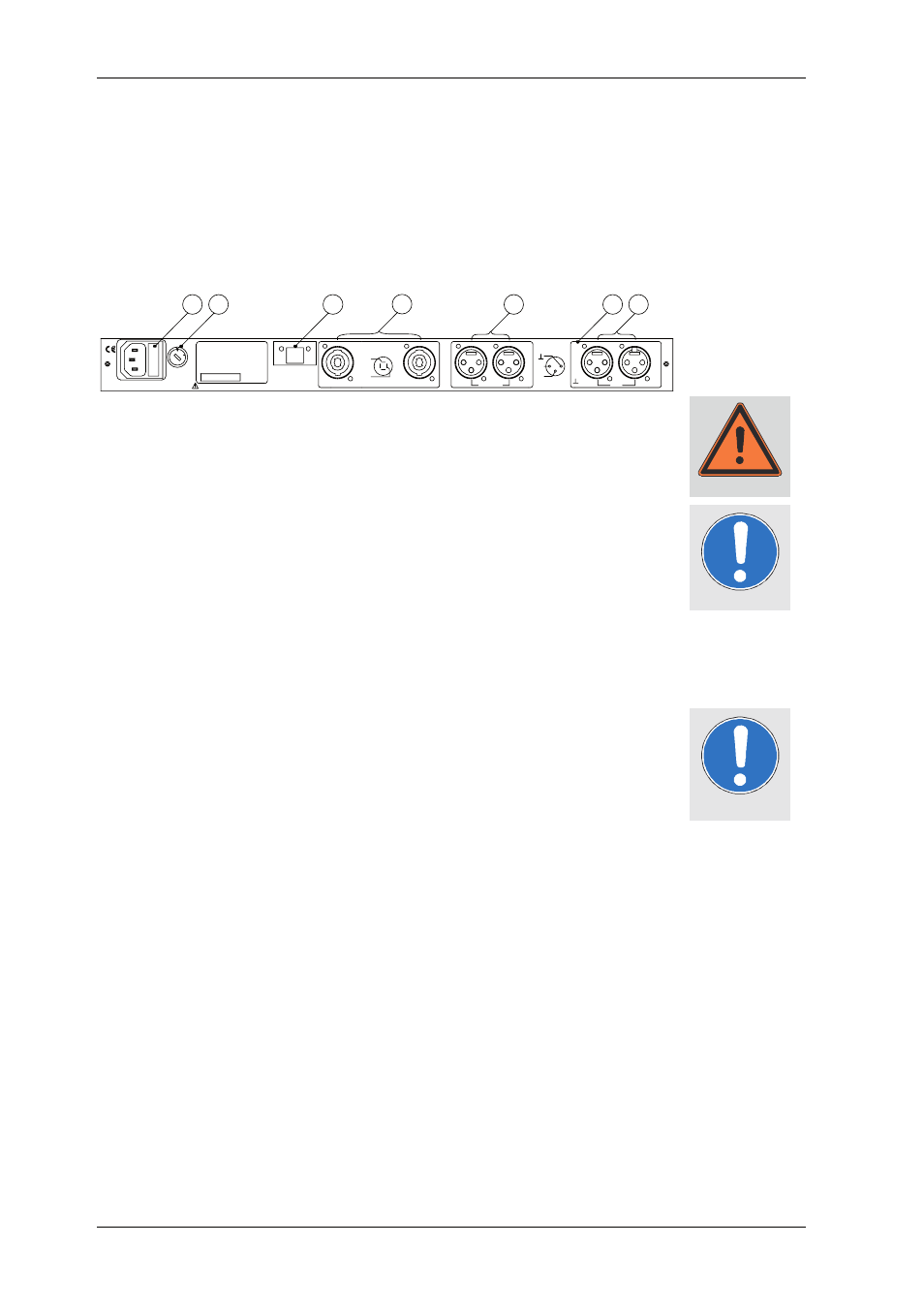
8)
FUSE
Fuse holder which is fitted with a 315 mA slow glass fuse in 230V mode. With 115V
operations, a 500mA slow glass fuse must be used. Never use a fuse with specifications
different than the aforementioned values. Never bypass the fuse holder. The system
controller can be irreparably ruined and/or even cause a fire.
9)
VOLTAGE SELECTOR
This switch is used to adjust the equipment to the desired operational voltage level of
115 or 230 VAC. WARNING: the equipment can be destroyed if the wrong operating
voltage level is selected!
10)POWER SEQUENCE SEND
About 1 second after switching on the ACCESS Controller, a control voltage of +15V is
present at both connector pins. If, for example, you have fitted your amp rack with
power amplifiers that have a remote control feature, then connect this output with the
SEQUENCE RCV input of the first amplifier, the SEQUENCE SND output of the first am-
plifier with the SEQUENCE RCV input of the second amplifier, etc. When turning on the
ACCESS Controller, all amplifiers will then be turned on time-delayed.
11)SENSE INPUT BASS A / BASS B
Two independent sense inputs, which drive a common limiter circuit. The amplified
output signal of the bass amplifier is connected to the pins 1- and 1+ of this Speakon
4-pin connector. This signal provides the controller with information for the bass-
limiter. Make sure that the Speakon connector clicks into place properly. All SENSE
inputs are galvanically insulated from the amplifier with balanced transformers.
12)BASS OUT
The electronically balanced BASS line level outputs are connected to the inputs of the
corresponding amplifier. We recommend using only high-quality connecting cables from
KLING & FREITAG. Bipolar shielded connectors should be used to connect the power
amplifiers. Connecting instructions are in the chapter ‘‘Pin Diagrams of Connectors and
internal Wiring’’.
13)GROUND LIFT
If the Ground Lift switch is set on LIFT, then Pin 1 of the INPUT connector is not con-
nected to the ACCESS C10 Controller. There is always a connection between the INPUT
(XLR male) and the LINK (XLR female) connector. If the C10 is operated with a K&F
Connector Panel, then this switch must be set on GROUND.
14)INPUT
The C10 Controller is equipped with a transformer balanced input. Use the XLR-female
connectors as input. The parallel connected XLR-male connector is used to link the sig-
nal to additional ACCESS controllers or amplifiers.
Rear
Warning
Important
Important
8
9
10
11
12
14
13
SENSE BASS A
I
N
P
U
T
LINK
3
1
2
2
1
3
XLR
L
I
T
F
+
3
-
B
A
S
S
O
U
T
1
2
PARALLEL
2
3
1
2
1
3
-
SENSE BASS B
+
1
+
-
2
IN
+
-
2
SPEAKON
1
50-60Hz / 30VA
115 / 230VAC
Made in
T 500 / T 315mA
CONTROLLER K&F ACCESS C10
READ MANUAL BEFORE USE
SEND (+15 V)
POWER SEQUENCE
Germany
Fuse 115 / 230V:
Power Requirements:
Serial Number:
KLING
2
3
0
115
SELECTOR
VOLTAGE
& FREITAG GmbH