9 the access connector panels, 1 connectors of the connector panels cp1 and cp3, The access connector panels – KLING & FREITAG K&F ACCESS T9 User Manual
Page 30: Connectors of the connector panels cp1 and cp3, Front
User’s Manual
ACCESS SYSTEM
KLING & FREITAG GMBH ©1995-2009
Version 6.0, 17.03.2009
Page 30 of 60
9.
The ACCESS Connector Panels
If you have ACCESS subwoofers with Speakon connector where both drivers
are connected in parallel at pins 1+ / 1- (standard connection since april 2009),
they can not be used with the ACCESS connector panel without further ado.
For ACCESS subwoofers with this pin assignment we recommend operation with the
digital system controller K&F CD 44 and the K&F System Rack. Please refer to the CD 44
user's manual.
In order to operate current ACCESS subwoofers (standard since april 2009) with the
ACCESS controllers C5 / C9 / C10 and the Connector Panels CP1 / CP3 / CP1-B / CP3-B
we recommend ordering subwoofer with the option 'EP5 connector instead of Spea-
kon'. With this option you can operate ACCESS subwoofers with the ACCESS control-
lers and the Connector Panels according to this manual.
9.1
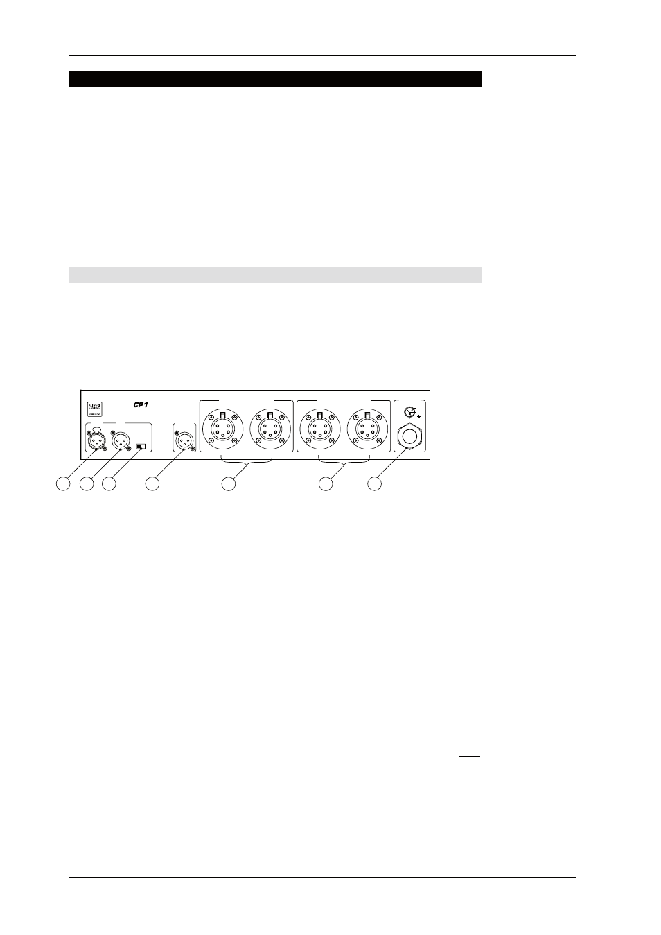
Connectors of the Connector Panels CP1 and CP3
1)
CP1
This model is designed to be connected to a 230 V mains supply.
The model with the code number ‘1‘ is recognizable by its power supply cable with
the blue plug on the front side of the equipment. (CEE 16 A, 3-pin, 230 V, 6 h)
2)
CP3
This model is designed to be connected to a three-phase supply current
with 230 V per phase. The model with the code number ‘3‘ is recognizable by its
power supply cable with the red plug on the front side of the equipment. (CEE 16 A,
5-pin, 400 V, 6 h)
2
3
1
NEUTRIK
PUSH
1
3
2
NEUTRIK
1
3
2
NEUTRIK
1
2
3
4
5
1
2
3
4
5
1
2
3
4
5
1
2
3
4
5
BASS SPEAKER OUT
INPUT
LINK
BASS OUT
GROUND
ON OFF
TOP SPEAKER OUT
MAINS
ACCES S
L / +
N
1
2
4
7
5
6
3
1)
INPUT
Balanced XLR input connector (female) for the input signal (e.g. the
signal from the mixing console)
2)
INPUT --- LINK
Balanced XLR output connector (male) to link the input signal
to other devices.
3)
GROUND LIFT
The Ground Lift switch serves to avoid ground loops. If the
Ground Lift switch is set on LIFT, then the Pin 1 (ground) of the input connector is
not connected to Pin 1 of the cable IN on the rear of the unit. There is always a con-
nection between the INPUT connector (XLR-female) and the LINK connector (XLR-
male).
4)
BASS OUT
This output provides the optional transmission of the bass signal
supplied by the C5/9 Controller (LINE) to an additional power amplifier.
5)
BASS SPEAKER OUT The bass speaker(s) are connected to these EP-5 connectors
(female). Both connectors are wired in parallel (no stereo signal!)
6)
TOP SPEAKER OUT
The mid-high speaker(s) are connected to the parallel EP-5
connectors (female) (no stereo signal).
7)
Central Power Supply Cable
7a)
The connector panel CP1 is equipped with a CEE connector 16A, 3-pin, 230V,
6h and serves as a connection to a 230V power supply. With this model, a total
of max. 16A can be connected to the 6 junction boxes.
7b)
The connector panel CP3 is equipped with a red CEE connector 16A, 5-pin,
400V, 6h and serves as a connection to a three-phase current power supply with
230V per phase.
Front