One Systems PT-10 User Manual
Page 5
One Systems, Inc. 6204 Gardendale Dr., Nashville, TN 37215
5
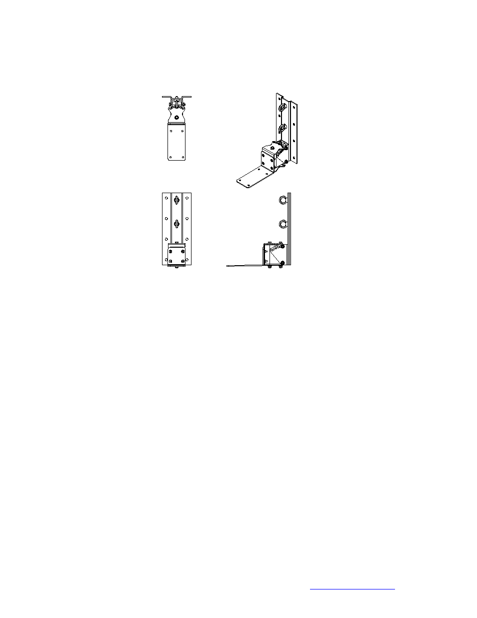
Figure 2
Prior to mounting the wall bracket to the wall the speaker mount section should be
removed. See Figures 2a and 2b.
NOTE: The M10 bolts associated with the “pan” axis should be left in place, as shown in
both Figures 2a and 2b.
The wall bracket section should now be mounted to the wall surface. The PT-76a has
12 mounting holes and the PT-38a has 8 mounting holes for allowing fasteners to join
the bracket and loudspeaker assembly to the mating surface.
IT IS NECESSARY TO USE ALL MOUNTING HOLES TO INSURE A SAFE AND
SECURE MATE TO THE ASSOCIATED SURFACE! (12 for the PT-76a and 8 for the
PT-38a)
All fasteners associated with the mounting of the Pan and Tilt bracket and loudspeaker
assembly to the mating surface are the responsibility of others. The design and
structural capacity of mating surfaces (such as walls) vary greatly and specific fasteners
are designed for use with specific mating surfaces. One Systems does not recommend
any mating fasteners and strongly urges the installer to consult with one experienced in
suspension of products from the specific mating surfaces and the appropriate choice of
fasteners for those specific surfaces.