Vacuum pump/brake line r – Paxton Superchargers Denali User Manual
Page 31
10-1
P/N: 4809639
©2004 Paxton Automotive
All Rights Reserved, Intl. Copr. Secured
12APR04 v3.0(01-03Denali/Esc(4809639v3.0))
Section 10
VACUUM PUMP/BRAKE LINE RELOCATION ('03 5.3L Vehicles
Equipped With Adjustable Pedals Only)
10.
FUEL PUMP/BRAKE LINE RELOCATION
A.
Disconnect the electrical plug from the top
of the vacuum pump. Unbolt and remove
the vacuum pump from the brake booster.
Disconnect the 1/2" hose from the barbed
nipple on the vacuum pump.
B.
Attach the vacuum pump to the supplied
pump bracket with the supplied 5/16"
hardware. (See Fig. 10-c.)
*** NOTE ***
For ease of installation, it may be easiest to remove
the driver’s side hood support and the plastic electri-
cal center cover.
C.
Unscrew the three nuts securing the small
computer style box on the driver’s side
firewall. (See Fig. 10-d.)
D.
Take the supplied 1/2" I.D. x 90° molded
hose and cut one end short. (See Fig. 10-
c.) Slide the cut end of the molded hose on
the barber end of the vacuum pump that
was inserted into the grommet in the brake
booster. Connect the 1/2" x 19" length of
hose to the 90° molded elbow with a 1/2"
hose mender. Secure the pump/bracket
assembly to the three studs using the same
three nuts removed in step C. Reconnect
the electrical connector to the vacuum
pump.
E.
Route the elongated hose underneath the
master cylinder over to the grommet in the
brake booster. Connect the 1/2" hose into
the grommet with the supplied plastic 1/2"
x 90° barbed fitting.
**** NOTE ***
When relocating brake lines, be sure that the brake
lines are clear of the steering column. Tie-wrap the
lines out of the way if necessary.
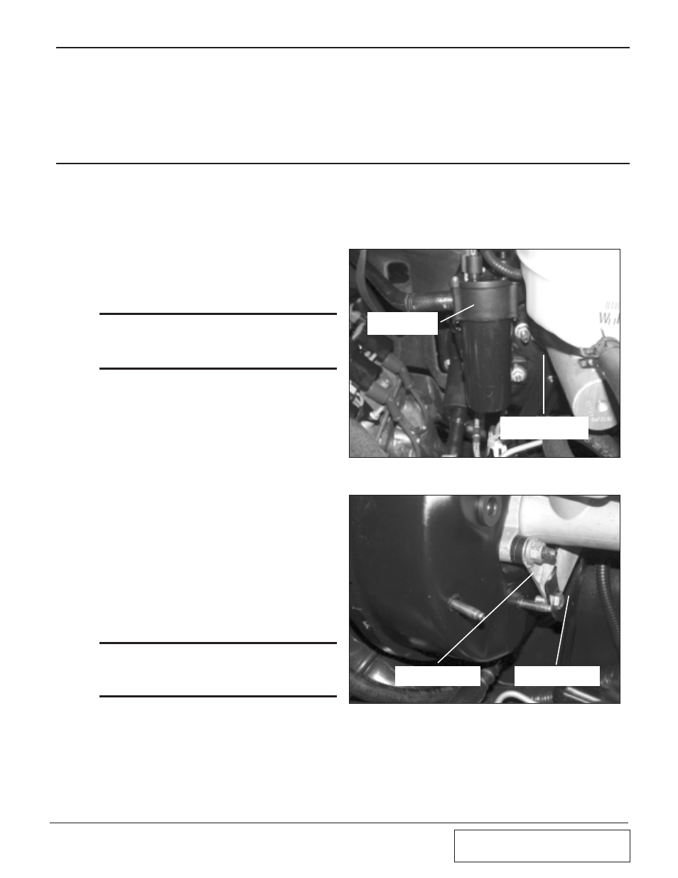
F.
Unbolt the bracket holding the lower brake
line assembly to the brake booster/master
cylinder attachment. (See Fig. 10-a.)
G.
Attach the supplied drop bracket to the
original bracket securing the brake lines
with the supplied 5/16" hardware. With the
new bracket added, push down the brake
lines and attach the new assembly to the
original two studs. This will drop the brake
lines making clearance for the inlet tube.
(See Fig. 10-b.)
Fig.
10
-a
Fig.
10
-b
BRAKE LINE BRACKET
RELOCATED
DROP BRACKET
INSTALLED
STOCK VACUUM
PUMP LOCATION
BRAKE LINE BRACKET
STOCK LOCATION