Paxton Superchargers Denali User Manual
Page 35
11-3
P/N: 4809639
©2004 Paxton Automotive
All Rights Reserved, Intl. Copr. Secured
12APR04 v3.0(01-03Denali/Esc(4809639v3.0))
11.B FUEL PUMP WIRING AND INSTALLATION, (2003 H2 Hummer)
A.
Remove the hood support from the passen-
gers’ side of the vehicle. Remove the plas-
tic cover from the power distribution cen-
ter. Unsnap the plastic casing surrounding
the fuses and relays. Mount the supplied
fuel pump relay on the lower plastic area.
Leave the hood support and plastic casing
off for installation of the water pump relay.
(See Fig. 11
.A
-f on page 11-2.)
B.
Connect the red 12-gauge wire from termi-
nal #30 to the supplied fuse holder using
the supplied butt connector. Install a yel-
low ring terminal on the other end of the
fuse holder and bolt to the fuse box power
supply terminal. (See Fig. 11.A-b.)
C.
Feed the yellow wire from relay terminal
#85 to the fuse box (electrical center).
Route the wire to the stock fuel pump
relay and connect using the supplied fuse
tap. Bend the fuse tap as shown in Fig.
11.A-c.)
D.
Run the black wire from terminal #86 on
the fuel pump relay to ground.
E.
With the long red 12-gauge wire connected
to the fuel pump relay terminal #87, route
the free end down to the area near the fuel
filter on the driver’s side inner frame rail
under the door. Secure as necessary to
avoid heat and sharp edges.
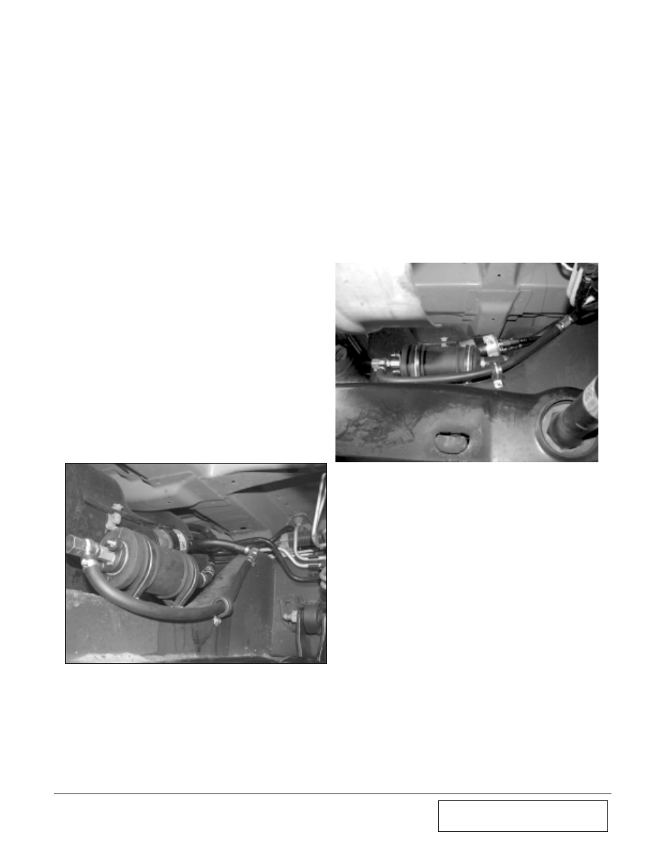
F.
Remove the fuel line from the inlet of the
fuel filter located on the driver’s side inner
frame rail directly in front of the fuel tank.
Mount the pump below the fuel filter on
the cross member taking care not to stress
the fuel lines. (See Figs. 11.B-a, 11.B-b.)
G.
Connect the male fuel fitting supplied in
the fuel pump assembly to the female fit-
ting removed from the inlet of the fuel fil-
ter. Connect the supplied 3/8" steel female
fuel fitting to the open barb on the fuel fil-
ter. Route the lines to avoid kinking in the
hose. Secure the discharge hose to the
cross member with the supplied adel
clamp. Secure any other hoses using tie-
wraps to avoid heat or sharp areas. (See
Figs. 11.B-a, 11.B-b, 11.B-c.)
H.
Attach the previously routed red wire to
the positive terminal of the fuel pump
using the yellow terminal connector. Use
the supplied black 12-gauge wire with yel-
low ring terminal to connect the negative
terminal on the fuel pump to a sufficient
ground.
Fig. 11.B-a
Fig. 11.B-b