Paxton Superchargers 5.2 Dodge Ram User Manual
Page 13
P/N: 4809625
©2003 Paxton Automotive
All Rights Reserved, Intl. Copr. Secured
25NOV03 v2.0 97-01 5.2/5.9 Dodge(4809625v2.0)
4-3
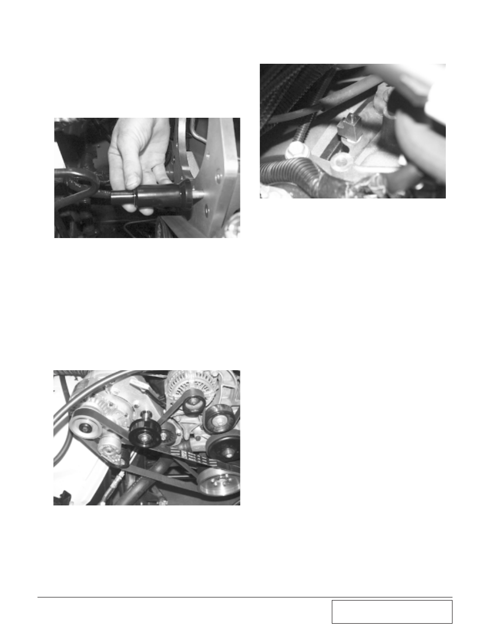
Fig. 4-j
Fig. 4-i
4-4
SUPERCHARGER INSTALLATION
A.
Install the idler Pulley Stand-off with the
hardware provided. Attach the supercharg-
er to the mounting bracket using the six
bolts provided.
C.
Install the straight fitting for the oil feed
using sealant on the threads. Re-install the
factory sending unit in the outlet of the
brass TEE facing up.
D.
Attach the 40" braided hose to the straight
fitting on the brass TEE and route the hose
toward the supercharger.
E.
Attach the 90° fitting to the supercharger
oil jet using sealant on the non-flared end
of the fitting.
4-7
OIL DRAIN
A.
Start by measuring down 2 1/2" on the
passenger’s side of the oil pan and make a
mark. From the second bolt from the front
of the oil pan, measure back 2 1/4" and
make another mark. In this location, drill
a 3/16" hole. With the hole drilled, take a
piece of wire and make sure that the rod
or crank is out of the way. You may have
to rotate the engine.
B.
With the punch provided, start to enlarge
the hole. You will need to use an air-ham-
mer for this. If you try to use a standard
hammer it will destroy the pan. Use anti-
seize on the punch. By doing this, the
punch will go in easier. Be careful to only
go as deep as the shoulder. Test fit the tap
as you go, so you don’t make the hole too
large. The hole should be Ø9/16".
C.
Using a 3/8 x 18NPT tap, begin tapping
the threads, but don’t go all the way in.
Remove the tap, apply sealant to threads
of the fitting provided.
D.
Attach 18" hose to the tap and secure it
with the supplied hose clamp. Route the
hose up to the supercharger and attach.
C.
Install the idler pulley on the idler pulley
stand off.
4-5
BELT TENSIONER
A.
Install the supercharger belt tensioner on
the supercharger. The tensioner mounting
plate is secured to the front of the super-
charger with the supplied countersunk fas-
teners, followed by the tensioner, which
should be oriented as shown in appendix.
B.
Route the supercharger belt as shown.
(See Fig. 4-k.)
4-6
OIL FEED
A.
Remove the oil sending unit. This is locat-
ed at the rear of the engine next to the dis-
tributor.
B.
Once you have removed the factory send-
ing unit, install the brass TEE that is pro-
vided.(See Fig. 4-j.)
B.
Install the idler pulley stand off. (See Fig.
4-i.)
Fig. 4-k