Dimensions, A - 14 – Pinnacle Systems CA User Manual
Page 22
- A - 14 -
Dimensions
Model CA Cascading Safety Light Curtain
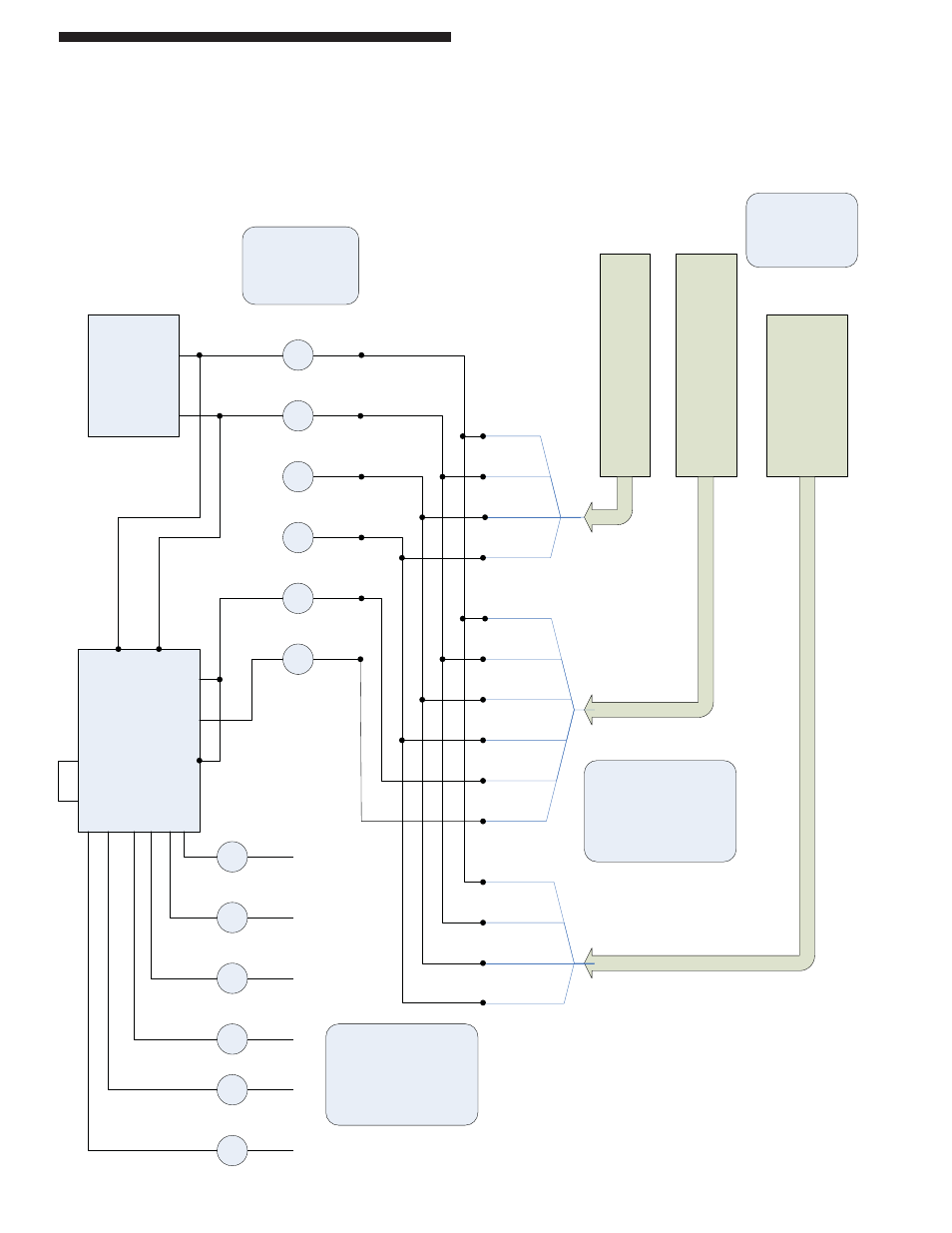
Figure 6: Wiring Diagram
Model CA 28-142 Wiring Diagram (with EDM)
Emit
ter
Pyl
on
Receiver
Pyl
on
OPTIONAL
Remote
Status
Display
&
Blanking
Customer
+24vdc @ 1A
Power supply
OPTIONAL
Model SSSR
Safety Relay Module
SNO4062k
Red
Red #1
Red #1
Red #1
Blk
Blk #2
Blk #2
Blk #2
OPTIONAL
Customer supplied
Terminal Strip
Wht
Grn
Blu
Brn
Wht #3
Wht #3
Wht #3
Grn #4
Grn #4
Grn #4
Blu #5
Brn #6
+24vdc
Ground
CAN_L
CAN_H
OSSD #1
OSSD #2
Dry Contact
#1 N.O. (held
closed)
A1
A2
Safety Outputs wire in
series with machine STOP
circuits
S12
S31
S35
13
14
23
24
OSSD outputs
24vdc = closed (green)
(.5A max each)
Only wire up to control
reliable (non-inductive)
circuits.
FSD outputs
RSD provides
message display,
Blanking, Latching
Relay, Cincinnati
interface
S22
S21
#1
#2
#3
#4
#5
#6
31 32
Dry Contact
#3 N.C. (held
open)
Dry Contact
#2 N.O. (held
closed)
NOTE:
SNO4063k =
N.O.