Installation of heater and flue pipe – Toyotomi FF-V30T User Manual
Page 26
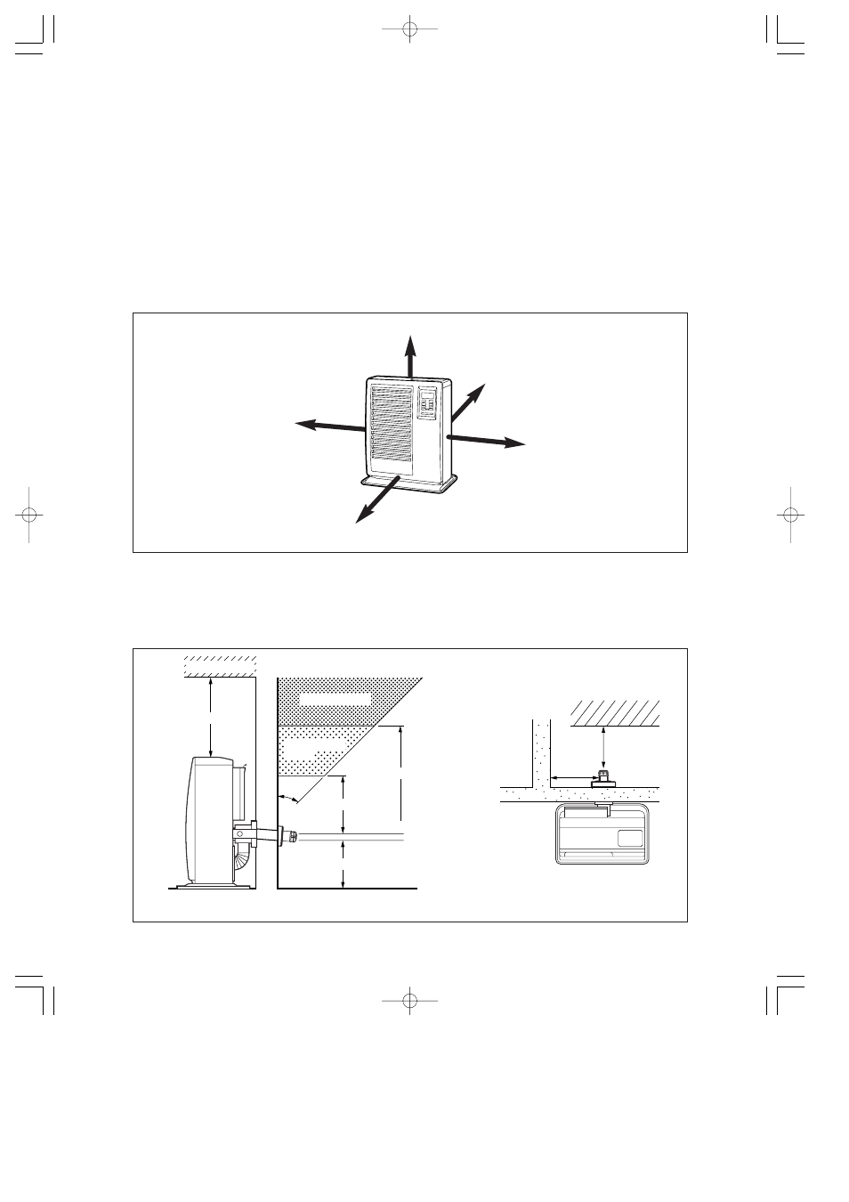
Flue Pipe Installation
Exhaust pipe
Not less
than 45 cm
Not less
than 45 cm
Not less than 60 cm
Not less than 60 cm
Not less than 30 cm
Not less than 20 cm*
45˚
Flammable object
Flammable object
Non-flammable
object
Fig. 1
More than 30 cm
More than 1.5 m
More than 30 cm
More than 10 cm
Fig. 2
Fig. 3
More than 60 cm
FF V30T
INSTALLATION OF HEATER AND FLUE PIPE
Before commencing any installation work, check that the proposed installation will comply with Building Code
requirements and Local Consent Authority rules that may apply to vented heaters in your area. (Check your
Local Authority website, or consult your Installer / Supplier.)
The Flue Pipe is designed to be installed through the wall of any conventional building cladding, including Brick,
Hebel, Linear, Gibraltar and Plaster Board, Tiles, Weatherboard, Plastered Polystyrene, and metal profiles etc.
The FF V30T heater is designed to be operated at altitudes up to 900 m, above sea level. For installation at al-
titudes between 900 m and 1800 m, adjustments by authorized serviceperson is necessary. Consult your sup-
plier for advice.
Select heater location. Ensure minimum clearances as indicated below between heater and nearest combustible
materials. (See Fig. 1.) Provide service access to clean the circulation air filter, integral fuel strainer and reset
button.
2.
Ensure the outdoor flue discharge area is clear of anything that might be affected by the hot flue exhaust gas.
(See Fig. 2 and 3.)
The Flue Pipe (as in Fig. 2), is for wall thickness from 130 mm to 320 mm.
A)
B)
C)
1.
25
FF_V30T_Type B_US.qxd 14.6.2 11:51 ページ 25