Rigging, 1 rigging overview – Adamson E-Series User Manual
Page 20
Page 20
Fig. 3
E12
E15
Fig. 4
0
0°
1
0.5°
2
1.0°
3
2.0°
4
3.0°
5
4.5°
6
6.3°
7
8°
R
in enclosure
0
0°
1
0.3°
2
0.6°
3
1.3°
4
2.0°
5
3.1°
6
4.4°
7
6°
R
in enclosure
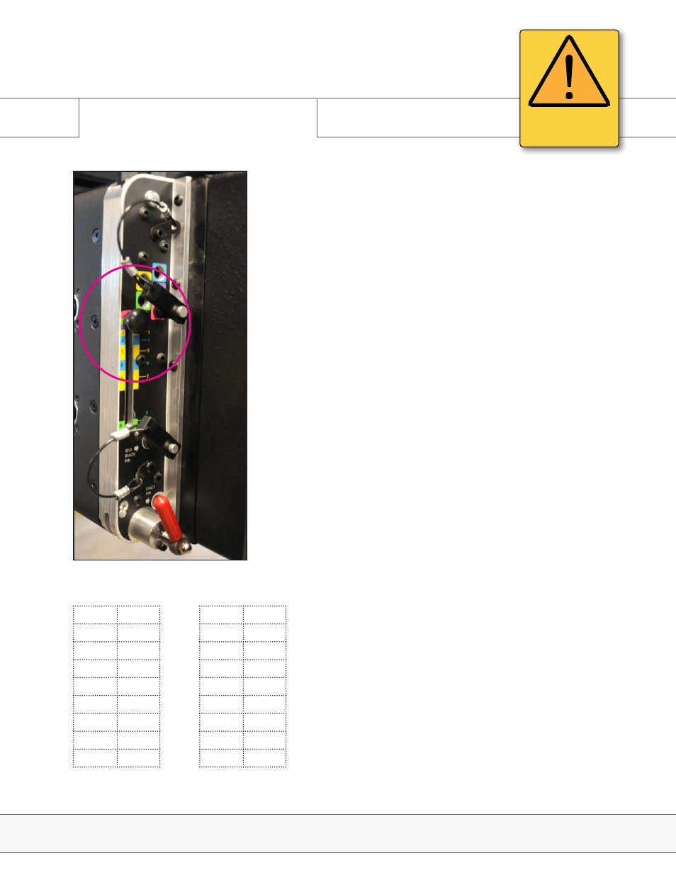
3.1 Rigging Overview
The rear of the E-Capsule also features an angle chart
with a knob lever which adjusts the angles. (Fig. 2) All
angles are set while the cabinets are stacked on the dolly,
ensuring that a single technician can prep the cabinets
for rigging. For a more detailed look at the rigging sticker,
please refer to section 3.4.
There are 8 angles, 0 to 7, and an additional ‘R’ being the
‘idle’ or ‘rest’ position, when the rigging hardware is all the
way down and the boxes aren’t connected. It is applicable
when the enclosure is not in use, to protect the rigging
hardware from damage. To keep the system intact for
transport, leave the angles pinned in.
The angles are numbered as well as color coded to mark
which slot should be pinned with the attached push-pin.
The following rigging positions are equal to the following
degrees for the E12 (Fig. 3) and the E15 (Fig.4).
Fig. 2
Rigging
E-Series | Rigging
ATTENTION
IMPORTANT OPERATING
INSTRUCTIONS