Rigging, 1 rigging overview – Adamson E-Series User Manual
Page 21
Page 21
3.1 Rigging Overview
Rigging
E-Series | Rigging
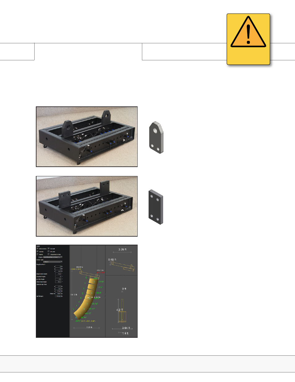
In standalone mode (Fig. 1), the frame can be
used to lift flat to slightly-angled arrays. Two
rigging plates are provided for dual motor
operation, and if two motors are not available,
one lifting plate may be repositioned towards
the center of the frame. Please refer to
Blueprint AV™ when determining proper lifting
plate location.
In order to attach the extended beam, the
lifting plates must be removed and replaced
with Extended Beam plates, characterized as
having a rectangular shape and two smaller
holes at the top of each plate. (Fig. 2)
As arrays get longer and more curved, the
center of gravity will shift, making it neces-
sary to position the rigging beam and rigging
pieces so that the motors carry equivalent
weight. The ‘Mechanical’ tab in Blueprint AV™
will aid the user in choosing the correct rig-
ging frame configuration. (Fig. 3)
Fig. 1
Fig. 2
Fig. 3
ATTENTION
IMPORTANT OPERATING
INSTRUCTIONS
The E-Frame with Extender Beam is designed for use with the E12 and E15 cabinets. It
consists of a steel frame, paired with an extension beamof which there are several combination
configurations. Always refer to Blueprint AV™ for correct rigging instructions.