Rigging, 10 rigging the e sub – Adamson E-Series User Manual
Page 35
Page 35
3.10 Rigging the E Sub
E-Series | Rigging
The E218 an E219 rigging system is based on the same concept as the Energia Autolock™ system, but simplified. A
less complex system without spring loaded locking mechanisms allows the user to quickly connect and fly a multitude
of E-Series Subwoofer cabinets.
The E-Frame Full Line has two modes; flying and stacking. A tray for the Adamson Laser Inclinometer exists at one
end of the frame. If the tray is facing forward, the frame is in flying mode. If the tray is facing backwards, the frame
is in stacking mode.
Fig. 1
Fig. 2
Fig. 3
Rigging
PINCH POINT
CAN CAUSE SEVERE
PERSONAL INJURY
WARNING
SAFETY RISK
PAY SPECIAL ATTENTION
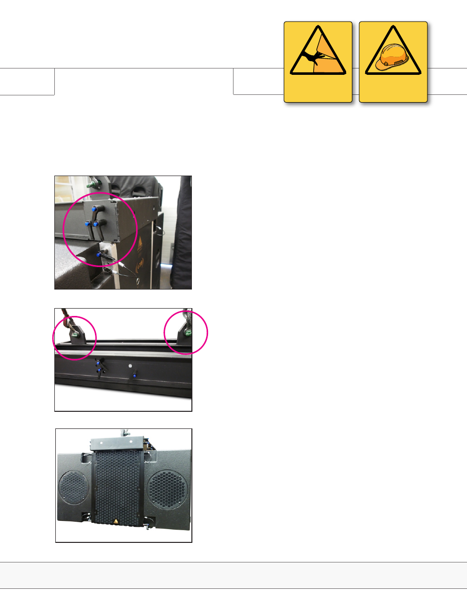
4. Lift the Frame with the E-Series Subwoofer attached. (Fig. 3) If
more E218 or 219 are to be flown, repeat step 1 for the next dolly,
lower the already rigged Subwoofers to the next set, position the
rigging pieces and secure them using the push pins.
3. Due to the depth of the E-Frame Full Line, no external beam is
needed. Attach rigging plates to the rigging frame in the positions
specified in the Mechanical page of your Blueprint AV™ design.
(Fig. 2)
Four rigging pieces drop down from the center capsule to connect
another E218, E219 , or an E-Frame Full Line to adapt for use with
an E12 as well. Four chambers at the top of the center capsule
allow connection between 2 E218 Steps to rigging the E-Series
Subwoofers:
1. Set the angle of all cabinets to be flown to either 0° or 3° splay, as
specified in your Blueprint AV™ design. (Note that in order to connect
the top box to the rigging frame, the angle must be set to 0°)
2. Attach the E-Frame Full Line to the top E218 or E219 cabinet and
secure in place with the push pins provided (Fig. 1)