Controling midra, Introduction, Physical interfaces – Analog Way MIDRA PLATFORM TPP Current Programmer's Guide User Manual
Page 6: Protocol, Picture 1 : rj45 leds colors definition, 2 controling midra, 1 introduction, 2 physical interfaces, 3 protocol
6
PROGRAMMER'S GUIDE FOR v01.02.11
2 CONTROLING MIDRA™
2.1 Introduction
Midra™ products are usually controlled by the user friendly RCS² or other high-end remote controller,
but a programming interface is also provided for automation applications.
A good practice is to setup the machine with the RCS² and then control it with a few basic commands
like “preset recalling” and “layer input change”.
2.2 Physical interfaces
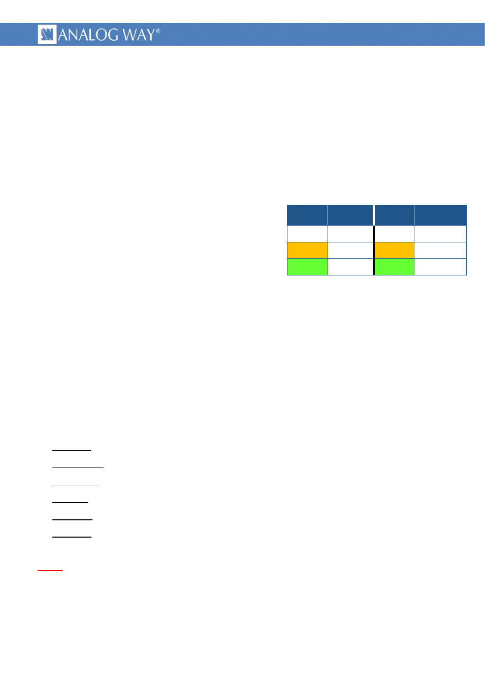
Picture 1 : RJ45 leds colors definition
Midra™ can be controlled through its rear Ethernet RJ45
plug :
labeled “ETHERNET”
10Base-T or 100Base-TX (Auto-Sensing)
MDI connection (which need a crossover cable to
connect it directly to a computer)
Midra™ can also be controlled through its rear RS232 DB9 female plug :
labeled “RS-232”
1200Bds up to 115200 Bauds
3 wires straight cable, 8 data bits, 1 stop bit, no parity bit, no flow.
2.3 Protocol
Supported protocol is TCP/IP, parameters can be set up with front panel or RCS² configuration menus.
Default values are :
Protocol :
TCP or UDP
DHCP client : no
IP address : 192.168.2.140
IP mask :
255.255.255.0
Gateway :
192.168.2.1
TPP port :
10500
Note : the simultaneous connection number is limited to 1.
Left LED
color
Definition
Right LED
color
Definition
Off
No link
Off
No activity
Amber
10 Mbps
Amber
Half-Duplex
Green
100 Mbps
Green
Full-Duplex