ATEIS ECS User Manual
Page 13
ECS MANUAL
Version EN.1
13
Lights when the ECS is switched on.
Normal status
Standby status
Error status
-Problem on the Ateïs Net.
-The ECS has no design inside.
-The design inside the ECS does not match with
the physical installation.
-If the link led is off :
The ECS has no input link
Power
LED
The LED grows
bright in green
The LED grows
bright in red
The LED flicks in red and green
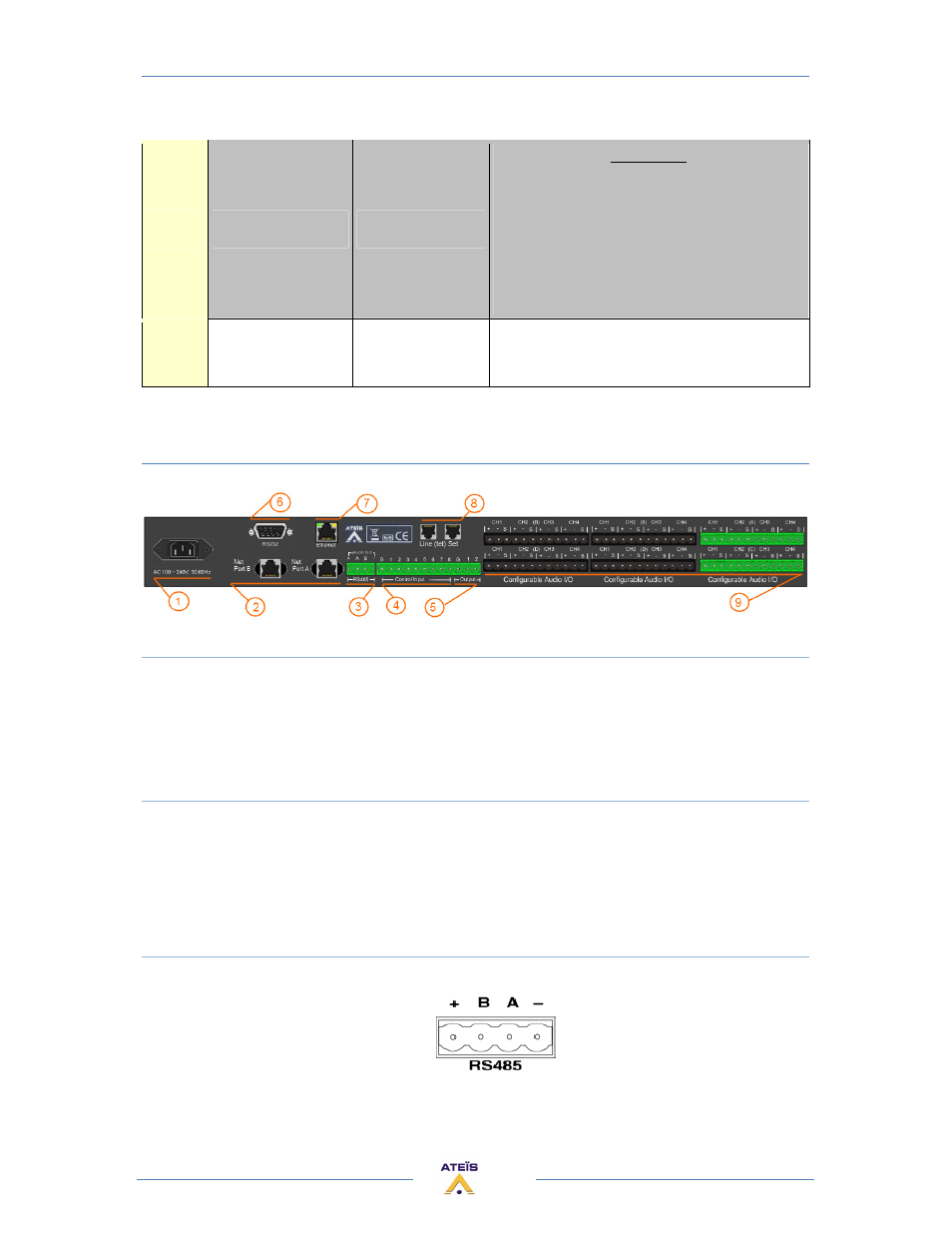
REAR PANEL
1) POWER SECTION
Insert provided power cable first into ECS then in the wall power connector.
Power switch:
• | (engaged) = ON;
• O (engaged) = OFF
2) LINK CONNECTORS
If you want to put several ECS in your rack (increase the number of input/output or remote
controllers) simply use straight CAT5 cable to connect “Net Port B” output to the "Net Port A” input
of the next sub-ECS. Close the loop by connecting the last ECS to the first one.
Note: this is not a network but a link: The maximum cable length is 10 meters between two ECS.
3) RS485 CONNECTORS
Here starts the RS485 network (connection for PPM and/or URC):
• Power: + and –
• DATA: A and B
The RS485 port at the rear side of the unit is used for additional units like the URC (Universal Remote
Controller) or the PPM (Programmable Paging Microphone).