ATEIS ECS User Manual
Page 16
ECS MANUAL
Version EN.1
16
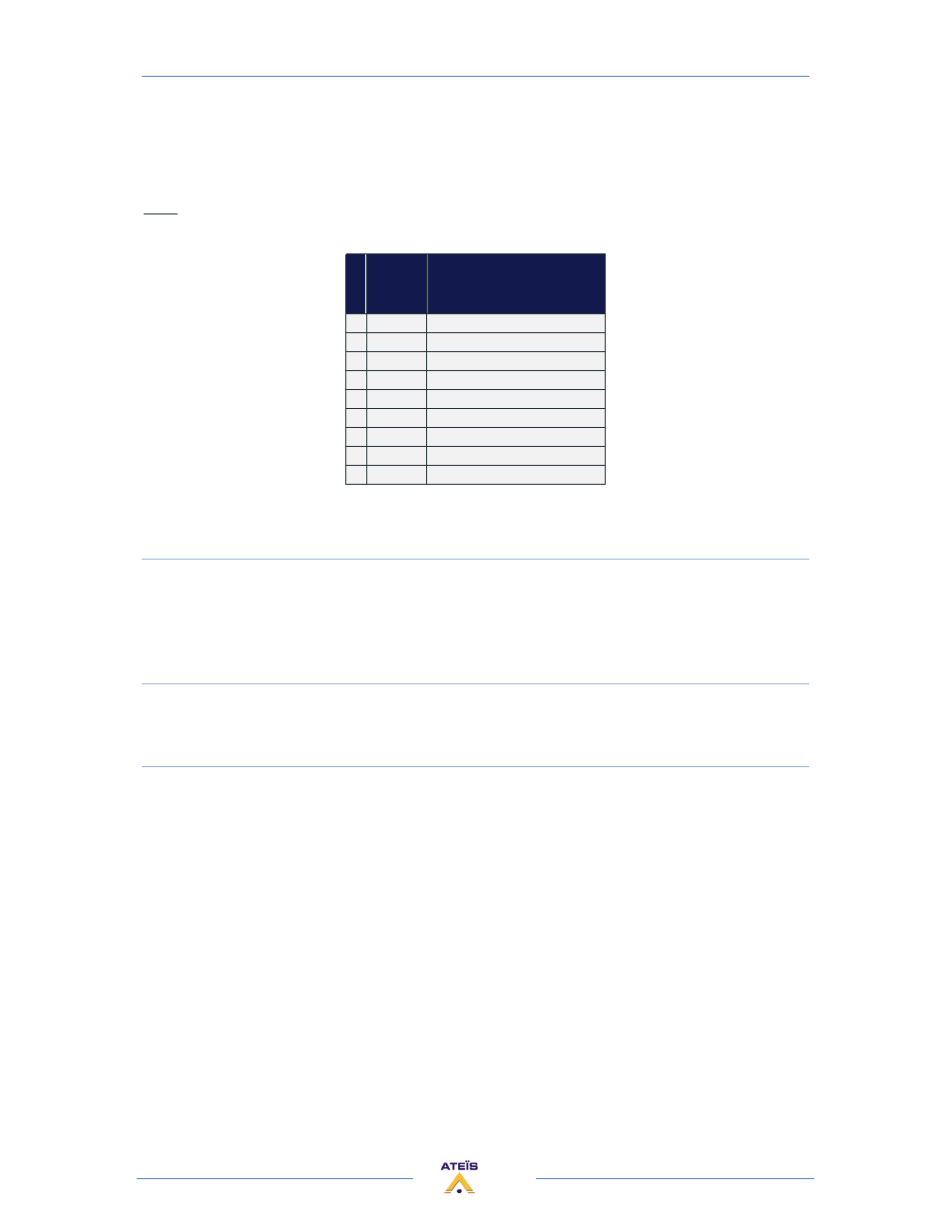
At the rear side of the ECS you also find a DB9f connector for RS232 data communication. This port
can be used for transparent RS232 data multipoint communication through the network (for using
with IDA4) or for 3rd party control applications.
Note:
RS232 does support cable lengths up to 15 m.
P
i
n
Signal
Text
1
CD
carrier detect (n.c.)
2
RXD
receive data
3
TXD
transmit data
4
DTR
data terminal ready (n.c.)
5
GND
ground
6
DSR
data set ready (n.c.)
7
RTS
request to send (n.c)
8
CTS
clear to send (n.c.)
9
RI
ring indicator (n.c.)
(n.c):non connected
7) ETHERNET (RJ45) CONNECTOR
For connecting the ECS in a TCP/IP based network or directly to a computer:
• To load design in a ECS system
• To pilot ECS system
• To monitor ECS system
8) TELEPHONE CONNECTOR
There are two connectors. One is to connect the telephone line. The other is to connect a
physical telephone, allowing you to have a physical interface in more than the software interface.
9) AUDIO INPUT/OUTPUT CONNECTOR
Balanced Audio input or output:
• S = Shield
• + = Hot audio signal
• - = Cold audio signal
Input and output cards have different connector colours:
• BLACK = OUTPUT
• GREEN = INPUT
If you want to use unbalanced signal please connect the Cold (-) pin with the Shield (S) pin.
There is a hardware clip operation on input board over 15dBu.