Installation, Vent requirements, Vent restrictor – Avalon Firestyles DVL Insert EF-2002 to 2005 User Manual
Page 11: For qualified installers only), Altitude considerations
Installation
(for qualified installers only)
1 1
Travis Industries
4 0 4 1 0 2 8
1 0 0 - 0 1 1 5 1
Vent Requirements
!
The gas appliance and vent system must be vented directly to the outside of the building, and never
be attached to a chimney serving a separate solid fuel or gas-burning appliance. Each direct vent gas
appliance must use it's own separate vent system.
!
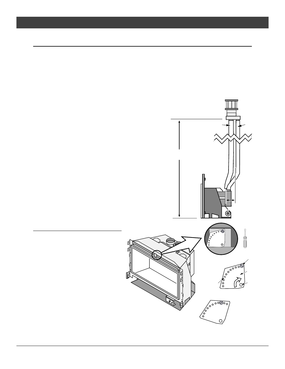
Make sure the exhaust pipe on the heater connects to the exhaust portion of the cap. The
illustrations below show how the flex liners should be attached.
•
The exhaust vent must reline the entire length of the chimney and terminate above the chimney top
!
Be careful not to crimp or rupture the liner when bending it into chimney offsets
•
When installed, the vent must meet all of the vent
manufacturer's requirements
•
Make sure to order the following:
-
4” UL 441 Gas Liner for Exhaust, 3” UL 441 Gas Liner
for Air Inlet
-
6-5/8” to 3” & 4” Co-Linear Adapter & Flashing
(Travis Part # 98900124).
-
Vertical Termination Cap (Dura-Vent pt # 991)
Altitude Considerations
This heater has been tested at altitudes ranging from sea
level to 8,000 feet (2,400 M). In this testing we have
found that the heater, with its standard orifice, burns
correctly with just an air shutter adjustment. If local codes
require resizing the orifice, in the U.S.A. refer to ANSI
223.1, Appendix P, in Canada B-149.1 or B-149.2
!
Failure to adjust the air shutter properly may lead to
improper combustion which can create a safety hazard.
Consult your dealer or installer if you suspect an
improperly adjusted air shutter.
Max. 1'
offset
Max. Ht. 35'
Min. Ht. 8'
Inlet
(3" dia.)
Exhaust
(4" dia.)
Vent Restrictor
WARNING: Restrictor adjustment should
only be done by a qualified installer.
Only those installations determined to
be over-drafting require this
adjustment. The best indication of
over-drafting is a hyper-active flame
pattern (flames that move too quickly).
If the air shutter is constricted, the
flames become short and yellow, yet
still very active. Over-drafting may
affect the pilot, but this is not the best
way to determine over-drafting. Over-
drafting is most likely in tall venting
configurations (especially if using an
“Exhaust Only Re-Line”). Do not
over-restrict the vent (this leads to
ghosting or lifting flames - reduce
restrictor setting).
To Adjust the Restrictor:
1
2
3
4
NOTE:
Position #1 is the
fully open position
Determine a restrictor position. Start low(move
the restrictor a maximum two positions at a time)
and thoroughly test the heater before adjusting further.
Remove the screw with a 1/4" nutdriver (or screwdriver).
Rotate the adjustment plate clockwise until the correct index hole is below the pivot point.
Insert the screw into the correct index hole and tighten.
1/4" Nutdriver
2
3
4
5
6
7
8
9
10
11
1
Adjustment
Plate
Index Holes
Pivot Point
Screw
Rotate the
adjustment
plate to change
the restrictor
position.
This restrictor is in
Position #3.