Application coordination, Application coordination -5, Figure 4-7. coordination timing diagram – Basler Electric BE1-50/51B-244 User Manual
Page 33
9252000793 Rev C
BE1-50/51B-244 Installation
4-5
Application Coordination
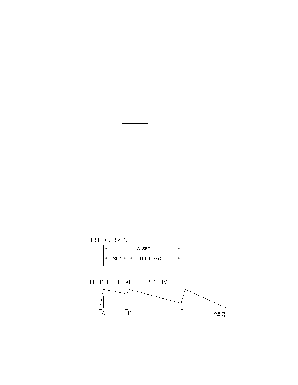
In a typical application coordination scheme, a BE1-50/51B-244 is used to provide primary protection for a
radial distribution feeder. An electromechanical overcurrent relay with extremely inverse timing provides
protection for the transformer and bus. To improve coordination with the electromechanical relay, the
BE1-50/51B-244 is configured with the following settings:
•
Integrating reset enabled (SW3-4 ON)
•
Westinghouse CO type curves selected (SW3-3 OFF)
The feeder reclosing relay is set for two reclose attempts at 3 and 15 seconds after the initial trip. If a
permanent fault occurs (magnitude 10 times pickup), calculate the feeder breaker trip time for each of the
three operations. Refer to Appendix A for the characteristic curve constants and definition of the terms
used in the following time characteristic curve equations.
From the time characteristic curve equation:
K
BD
C
M
AD
T
N
T
+
+
−
=
028
.
0
)
2
02758
.
0
(
1
10
2
7624
.
7
0938
.
2
+
×
+
−
×
=
= 0.209 seconds
From the reset characteristic curve equation:
1
M
RD
T
2
R
−
=
M equals 0 if current goes to zero. A negative result indicates reset time.
seconds
15.5
1
0
2
7.75
2
−
=
−
×
=
Result: Full trip = 0.209 seconds and full reset = 15.5 seconds if current goes to zero.
In Figure 4-7:
T
A
= 0.209 seconds (relay was at reset)
T
B
= value<T
A
because rewind has not gone to zero
T
C
= value<T
A
because rewind has not gone to zero
Figure 4-7. Coordination Timing Diagram