Manual trip, Model be1-50/51b-238 (one ampere sensing input), Time overcurrent (51) pickup – Basler Electric BE1-50/51B-237 User Manual
Page 43: Manual trip -5, Model be1-50/51b-238 (one ampere sensing input) -5, Time overcurrent (51) pickup -5, Figure 5-4. target indicator test setup
9252000899 Rev B
BE1-50/51B-237/-238 Testing
5-5
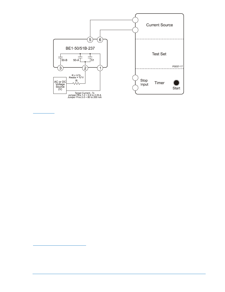
Figure 5-3. Target Indicator Test Setup
1. Configure the relay for manual trip testing:
Manual Trip
a. Connect the test setup as shown in Figure 5-1.
b. Set circuit board switch SW3 as follows:
SW3-1 = ON for 50 Hz operation or OFF for 60 Hz operation
SW3-2 = OFF (no additional time delay for the 50-A element)
SW3-3 = ON (GE IAC type characteristic curves)
SW3-4 = ON (integrating reset characteristic)
c. Set TIME DIAL to 0.0
d. Set CURVE to S.
e. Set TIME PICKUP to 1.0.
f. Set INST PICKUP (50-A) to 90.
g. Set INST PICKUP (50-B) (accessed at the top side of the assembly) to 20 (2.0 Aac).
2. Apply 0.9 Aac to terminals 5 and 6 (0.9 Aac provides relay operating power but is below the pickup
threshold.)
3. Connect a jumper to the Time Overcurrent Manual Trip jacks. Verify that the stop input of the test set
timer recognizes a 51 contact closure.
4. Remove the jumper and the current applied at relay terminals 5 and 6.
5. Apply 0.9 Aac to terminals 5 and 6.
6. Connect a jumper to the Instantaneous Overcurrent Manual Trip jacks. Verify that the stop input of
the test set timer recognizes a 50-A contact closure
7. Remove the jumper and the current applied to relay terminals 5 and 6.
8. Reset targets.
Model BE1-50/51B-238 (One Ampere Sensing Input)
1. Connect and configure the relay for 51 pickup testing:
Time Overcurrent (51) Pickup
a. Connect the test setup shown in Figure 5-4.
b. Set circuit board switch SW3 as follows:
SW3-1 = ON for 50 Hz operation or OFF for 60 Hz operation
SW3-2 = OFF (no additional time delay for the 50-A element)