Coordination with feeder 51 relay for fault 1 – Basler Electric BE1-51/27C User Manual
Page 63
9137200998 Rev E
57
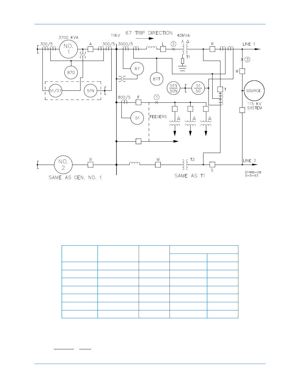
Figure 36. System Example
Downstream current in Table 4 is the current in the downstream relay with which the BE1-51/27C
elements must coordinate. The currents are the changes resulting from the fault assuming a driving point
voltage of 11 kV. Actual currents will be the sum of the table values plus the pre-fault load currents.
Transient level currents are based on use of the generator transient reactance. Steady-state level
currents are based on use of generator steady-state reactance and assuming no generator regulator
boost. Note that the table values apply for 3-phase faults. Transient level currents in generators for a
phase-to-phase fault will be about equal to the 3-phase current values. Steady-state level currents in the
generators will be higher for a phase-to-phase fault.
Table 4. Three-Phase Fault Currents
Level
Out of Service
Fault Loc.
Fault Current - A @ 11 kV
Downstream
Generator
Transient
T2
1
7256
776
Steady State
T2
1
5961
129
Transient
―
2
7256
776
Transient
T2
2
1552
776
Steady State
T2
2
258
129
Transient
―
3
713
713
Steady State
―
3
127
127
Coordination with Feeder 51 Relay for Fault 1
(1)
Multiples of pickup in 51 relay at transient level:
(
)
7.6
960
7256
6
800/5
7256
=
=
BE1-51/27C
Tests and Adjustments