Mechanical assembly of the basic module – BECKHOFF CX9000 User Manual
Page 37
Assembly and connecting
Embedded PC
35
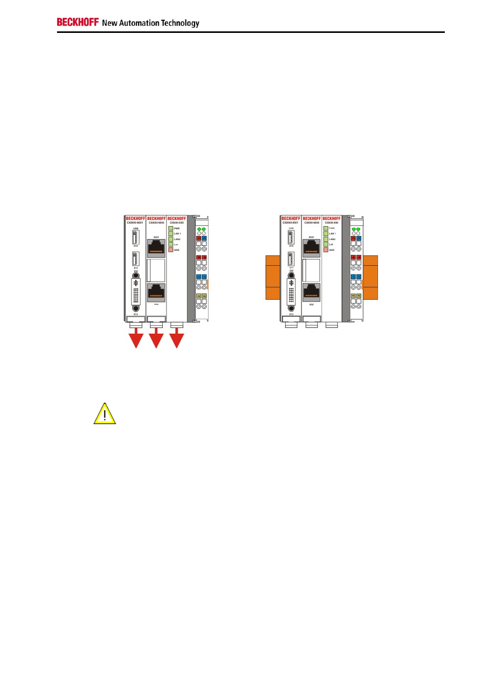
Mechanical assembly of the basic module
The installation of the modules takes place in three steps:
1. The sequence of the modules
The basic CPU module with system interfaces, which are factory-installed on the left side, is extended with the power
supply unit on the right and with the fieldbus connection (master or slave) left side if available.
2. Engaging on the top-hat rail
On the bottom of the modules, there is a white tension strap, which is connected with a latching mechanism. These
tension straps must be pulled down before attaching to the top-hat rail. This can be done using an ordinary
screwdriver and a slight turn.
Then fix the CX9000 block on the top hat-rail using the latching straps. You should hear a soft click.
Do not force the module or apply
excessive pressure!
Only apply pressure at insensitive points of the housing (edges). Never apply pressure on the display, the buttons or
movable parts of the CX-System.
After successful latching on the top-hat rail the straps should be pushed back to their original position.
Note:
A locking mechanism prevents the individual housings from being pulled off again. Detailed information relating to
disassembly of the CX-SYSTEM configuration from the top-hat rail can be found on page "Removal and disposal".