Maintenance, Wheel and drive gear – Brinly STH-420 BH Lawn Sweeper User Manual
Page 21
1009727-A
21.
MAINTENANCE
================================================================================================
53
50
46
42
44
45
62
59
65
57
58
56
61
63
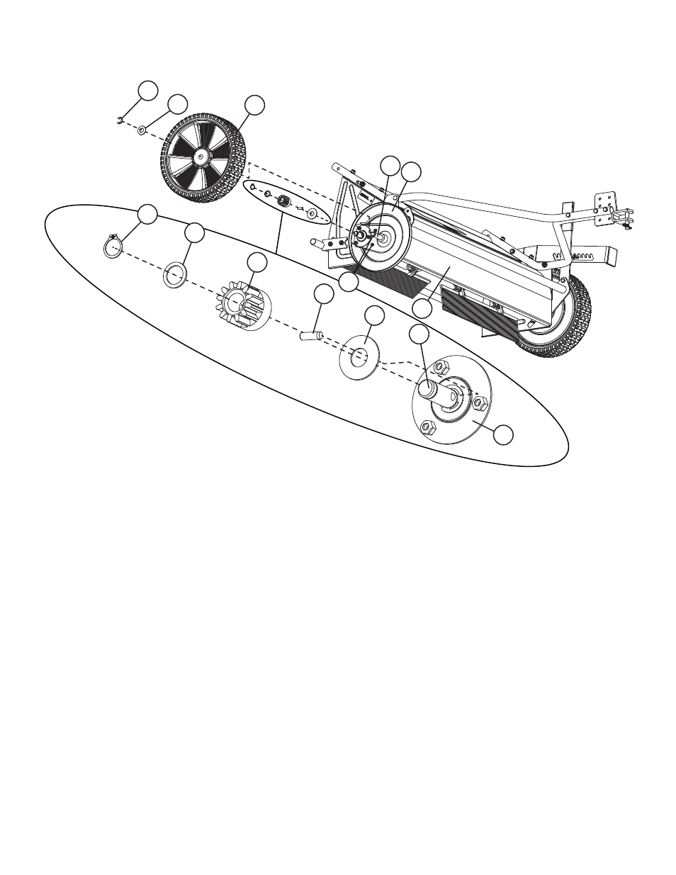
Wheel and Drive Gear
Disassembly and Inspection
1.
Stand the sweeper in storage position on a clean fl at surface such as garage fl oor or sidewalk (do not hang hamper from clevis assembly)
2.
Using a medium fl at tip screwdriver, remove E-Ring (53)
3.
Remove Machine Bushing (50) and Wheel (46)
4.
Inspect Wheel gear and Wheel Axle hole for damage and wear
5.
Inspect Wheel Axle (44) for damage and wear. Note: Wheel Axle (44) can be removed from the inside of the brush housing.
6.
Clean any dirt or debris from the inside of the Wheel (46) and Dust Cover (42)
7. Confi rm the Tapping Screws (63) holding the dust cover in place are not loose. Warning: Do not over tighten!
8.
Remove Retaining Ring (62) from recess in drive pinion gear. This example shows the RH Drive Pinion or (65).
9.
Remove Flat Washer (59) and Drive Pinion (65). Note: Cup one hand under the Drive Pinion during removal as the Dowel Pin (57) may fall free.
10. Inspect and clean the inside of the Drive Pinion. Note that the bottom of this gear has ‘R’ emboss into it, indicating the RH Drive Pinion.
11. Remove the Dowel Pin (57) from the Brush Axle (56) (if it has not already fallen free).
12. Inspect and clean the Dowel Pin
13. Inspect and clean the Dowel Pin hole on the brush axle. A small rag or paper towel can be used to clean the inside of the hole.
14. Remove the Large Flat Washer (58). Inspect and clean the washer and the area around the Brush Axle (56).
If Bearing Retainer (61) replacement is needed, continue with Step 15.
If Bearing Retainer (61) does not need replacement, continue at ‘Assembly and Lubrication’ section.
15. If Bearing Retainer (61) replacement is needed, remove Tapping Screws (63) and Dust Cover (42).
16. Remove E-Ring (53) using a medium fl at tip screwdriver.
17. Remove the Lock Nuts (20) securing the Bearing Retainer. Note: Do not let the Carriage Bolts (48) fall out of the Lower Pivot (43) side plate.
18. Remove Bearing Retainer (61)