Assembly – Brinly STH-420 BH Lawn Sweeper User Manual
Page 8
1009727-A
8.
ASSEMBLY
================================================================================================
68
3
4
32
14
25
68
4
32
14
25
3
7”
8”
9”
10”
11”
12”
13”
14”
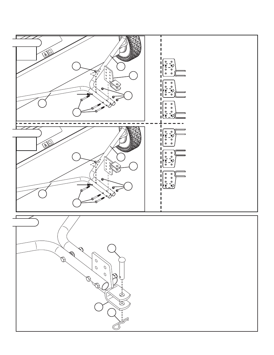
Using the rounded measurement from
the previous section, determine the
correct Clevis Assembly (68) mounting
holes from the diagrams directly to the
left
Note that hitch plate heights between
7” and 10” have the Clevis at the
bottom of the bracket and hitch plate
heights between 11” and 14” have the
Clevis at the top of the bracket.
Once the correct Clevis Assembly (68)
mounting holes have been determined,
attach the Clevis Assembly (68)
between the Right and Left Tow Tubes
(3 & 4) using the hardware in Panel 02
as shown in Figure 02.
Do not tighten at this time.
Use the remaining hardware from
Panel 02 and attach the Right and
Left Tow Tubes (3 & 4) at 3rd hole as
shown in Figure 02.
Note: Hitch
clevis at bottom.
3rd
Hole
3rd
Hole
Note: Hitch
clevis at top.
23
30
68
Figure 02
Figure 02
Figure 03
Tighten all hardware used in Figure 01 (6 Carriage
Bolts and Nuts) and Figure 02 (3 Hex Bolts and Nuts).
Using the hardware in Panel 03, attach Hitch Pin (23)
and Hairpin Cotter (30) to the Clevis Assembly.
Height
7”-10”
Height
10”-14”
Hitch
Height
Clevis Mount
Holes