BUG-O Systems BGW-5000 User Manual
Page 24
24
Two methods for tank tracking:
On the ground
1.
Loosen the bolts, and use a soft faced hammer, wooden mallet, dead blow hammer or a normal
hammer with a block of wood in between to “tap” the drive wheels into position so that they are set to
the correct radius. You can check these on the ground by making a cardboard template of tank radius
or use what we call a “sweep” or “radius” board if they have one- this is a template that tank builders
used to check the shape of a vertical weld joint during and after welding- its usually a piece of steel
with the tank radius cut on one face.
In the air/on tank
2.
Loosen the drive wheel “pivot” bolts on the ground (x 2 through the machined curved slot in drive
wheel housings)
Place the AGW in position in the tank and drive it around for a short distance- this should self- adjust
the wheels to tank radius-if it does not use a hammer as above or crowbar to position the wheels to
match the tank radius.
Just remember that even with the adjustment bolt loosened the tank drive wheels cannot come off and as
the machine is straddling the tank.
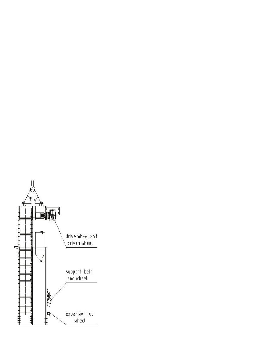
When all components of the GIRTH WELDER are in place, hook up the lifting eyes at the roof of the
GIRTH WELDER with crane and lift the frame off the ground, then hang the drive wheels on top of
the plate wall and lower it down, so the flanged wheel would land on one of the shell plates top edge.