BUG-O Systems BGW-5000 User Manual
Page 30
30
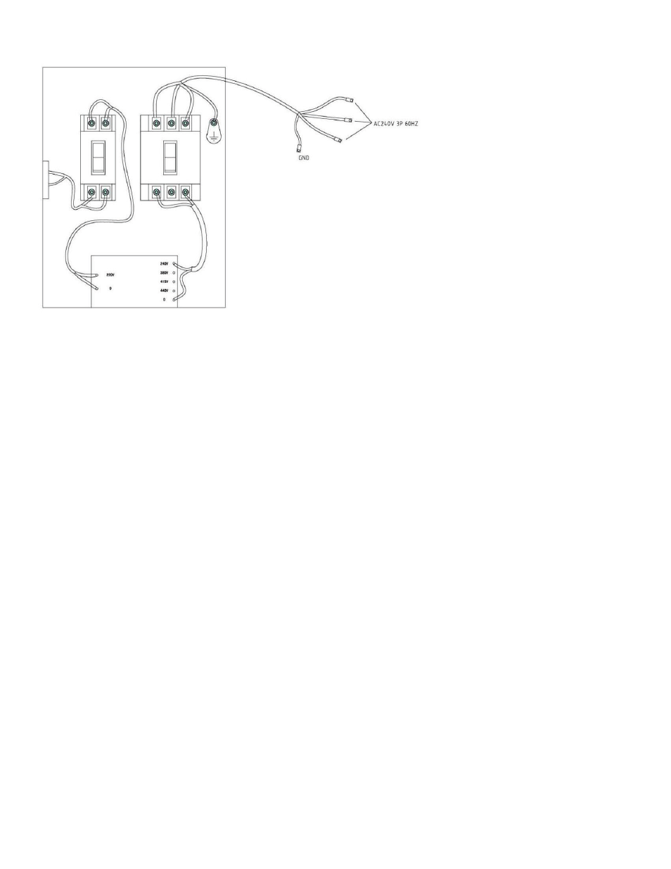
Example: non-standard input at 240V/3ph/60Hz connection.
4.5 OPERATION
1. Turn on the main power switch at the base of the power supply.
2. Turn on the main control with the switch located on the top right of the control panel.
3. Switch on the welding power source.
4. Positioning the flux belt system roughly 2-3 inches below the weld seam giving ample room to move the
flux belt in and out to the exact position. By having the belt a little lower will remove some of the burning
to the belt that may occur during the welding process.
5. Adjust the angle of the torch to roughly 15 degrees with a “Stick-out ¾" to 1" wire. Make sure that the tip
of the wire is roughly a ¼ inch from the surface to be welded (bottom of the bevel or area to be welded).
6. Ensure that the laser pointer is aligned with the tip of the soldering wire, we suggest you use a level to
get it as close as possible.
7. Program the parameters of welding (voltage, amperage and forward speed). NA-3 feeder switch
must
be in the “ON” position. Also make sure all emergency stop buttons are disengaged and that all
breakers are in the correct position in the main power supply.
8. Cover wire and seal with a generous amount of flux. Wire should be completely covered in flux.
9. Switch on electrical flux hopper valve.
10. Turn on the lamp and vacuum flux on the main power source.
11. Place the switch of speed at the position of “WELD”.
12. Test first that the direction is correct and setup is proper before welding and before placing flux on belt to
alleviate waste.
*** Test all the switches on the master control panel and monitor the LEDs (the LEDs are only available for