BUG-O Systems BGW-5000 User Manual
Page 25
25
Note: For double sided unit, operator is required to expand the
hydraulic jack above the operator platform to “open up” the
hinged master and slave frame, allowing the opened “A” frame of
the double sided unit to straddle on the shell plate.
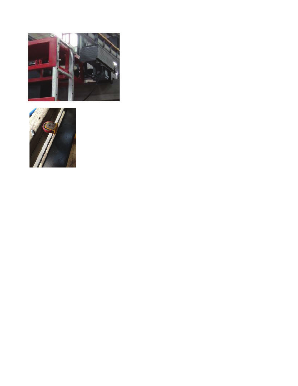
4.3.1 While loading, angle between the lifting cable and the horizon should not be
greater than 60°. The guide wheels should be extended to the maximum extension
with the hand wheel, and then bolted at the position perpendicular to the ground
surface. It provides a moving support to the frame and prevent impact between the
flux belt systems and weld head to the shell plate during handling.
4.3.2 When the Girth welder is securely straddled on the shell plate, retract the support guide wheel by
hand, wheel and then bolt the orientation of the support wheel to the horizontal position.
The weight of the Girth welder should then be supported by the flanged metal wheel at the top as well as the
flux belt assembly.
4.3.3 The welding power supply is intended to be located on the floor in the center of the storage tank. All of
the cables are run from the power supply to the cable hanger at the roof of the machine frame.
All cable connections are made at this point and the hanger clamp fastened in a way that the connections
themselves do not feel the strain of the cable weight.
4.3.4 Locate the power supply storage near the center of the tank. The storage case contains the main
power distribution disconnect, distribution transformer, and the welding power supply.
4.3.5 Procedures of transformation from top down GIRTH WELDER to bottom up one