Chapter 3 - hardware installation, Board layout, Block diagram – DFI BT9A3 User Manual
Page 10: A / b, Atom e3800 series /celeron, Intel atom
www.dfi .com
Chapter 3 Hardware Installation
10
Chapter 3
Chapter 3 - Hardware Installation
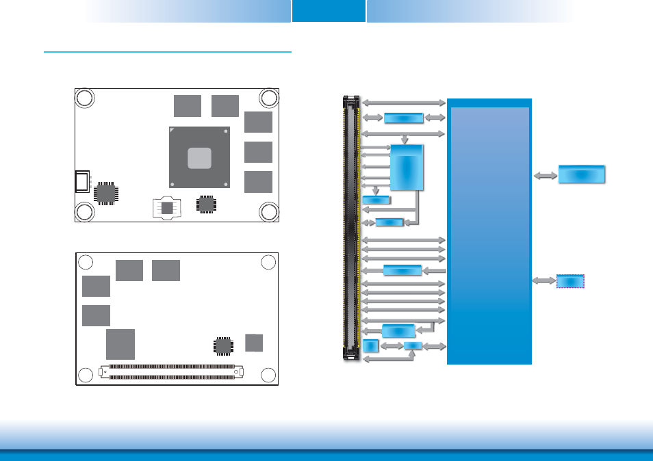
Board Layout
Top View
Bottom View
Block Diagram
EEPROM
USB 2.0 4x
SATA 2.0 2x
A / B
USB 2.0 4x
SATA 2.0 2x
SM Bus
Atom E3800 Series
/Celeron
eMMC
(Optional)
MMC Bus
Intel
®
GLAN
I210
PCIe x1 (Opt.)
GLAN
SPI
Flash
DDI Port 1
LVDS
DDR3L 1GB ECC
8x memory down
DDR3
1333MHz
Single Channel
D
PTN3460
PCIe x1
DDI Port 0
DDI Port 0
PCIe x
PCIe x1 (Opt.)
G
USB4604I
USB 2.0 4x
USB HSIC
HD Audio
LPC Bus
HD Audio
LPC Bus
Embedded
Controller
IT8528
8-bit DIO
WDT
I
2
C Bus
Serial Port 1, 2
Tx/Rx
System Fan
PWM/TACH
SLP/LID
WDT
S /
DIO
TCA6408A
T
USB 3.0 1x
USB 2 0 4x
USB 3.0 1x
PCIe x1
PCIe x1
PCIe x1
PCIe x1
PCIe x1
PCIe x1
Switch
Flash
E3800 Series
Intel Atom
DDR3L
DDR3L
DDR3L
DDR3L
DDR3L
SPI Flash BIOS
CPU fan
1
NXP
PTN3460
Intel
WGI210AT
DDR3L
DDR3L
DDR3L
DDR3L
eMMC
(optional)
SMSC
USB4604
ITE
IT8528
B110
B1
A110
A1
COM Express connector