Installing the com express debug card, Chapter 3 – DFI BT9A3 User Manual
Page 23
Advertising
www.dfi .com
Chapter 3 Hardware Installation
23
Chapter 3
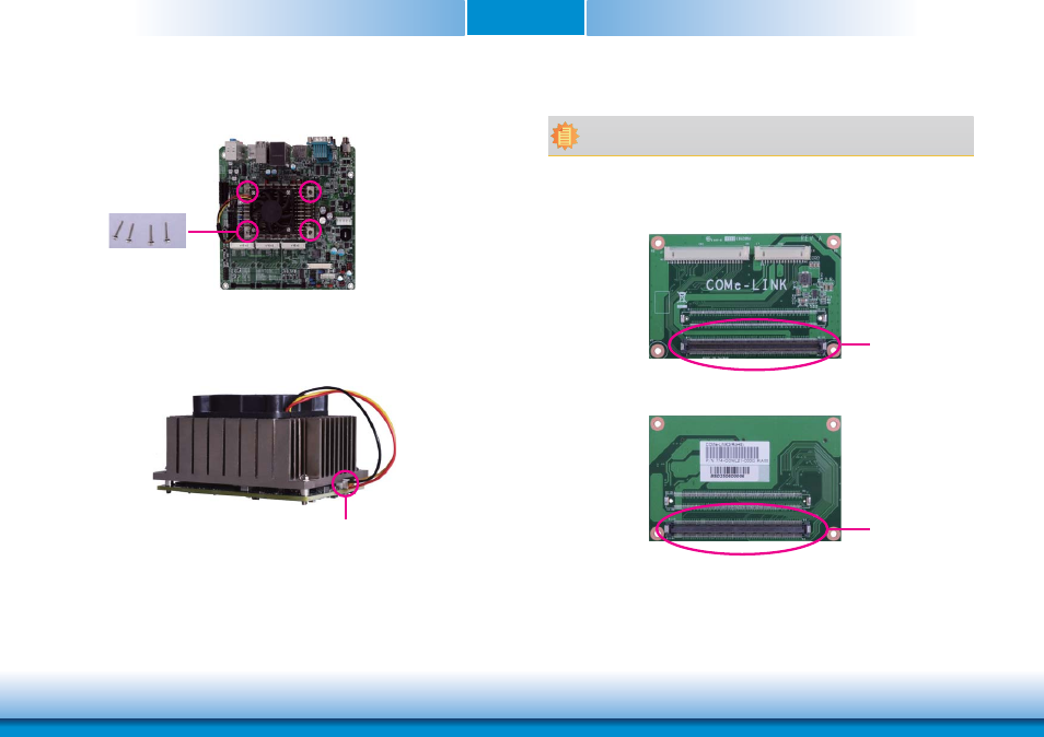
8. Use the provided mounting screws to secure BT9A3 with heat sink to the carrier board
and then connect the cooling fan’s cable to the fan connector on BT9A3. The photo below
shows the locations of the long mounting screws.
Long screws
9. And then connect the cooling fan’s cable to the fan connector on BT9A3.
Fan connector
Note:
The system board used in the following illustrations may not resemble the actual
board. These illustrations are for reference only.
1. COMe-LINK2 is the COM Express debug platform installed into COM Express Mini modules
for the application of debugging and displaying signals and codes.
COM Express
Connector
COM Express
Connector
Installing the COM Express Debug Card
Advertising