Cooling option, Installing bt9a3 onto a carrier board, Chapter 3 cooling option – DFI BT9A3 User Manual
Page 21
www.dfi .com
Chapter 3 Hardware Installation
21
Chapter 3
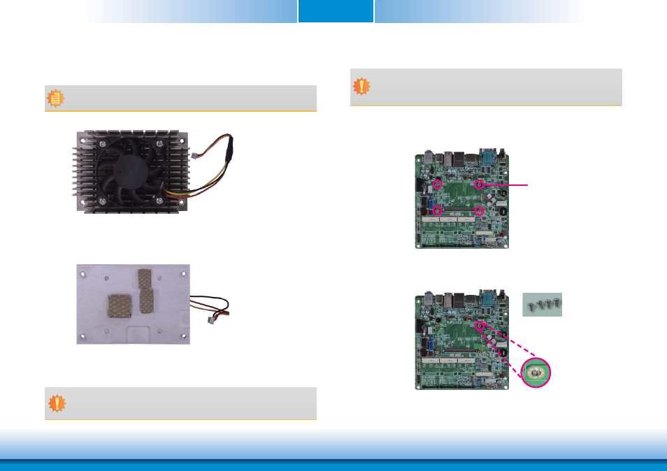
Cooling Option
Heat Sink with Cooling Fan
• “1,” “2“ and “3” denote the locations of the thermal pads designed to
contact the corresponding components that are on BT9A3.
Top View of the Heat Sink
Important:
Remove the plastic covering from the thermal pads prior to mounting the heat sink
onto BT9A3.
Note:
The system board used in the following illustrations may not resemble the actual
board. These illustrations are for reference only.
Bottom View of the Heat Sink
Installing BT9A3 onto a Carrier Board
Mounting hole
1. Now install the module and heatsink assembly onto the carrier board. The photo below
shows the locations of the mounting holes on the carrier board.
2. Insert the provided mounting screws into the mounting holes - from the bottom through
the top of the carrier board.
Mounting screws
• To download COM100-B datasheet and manual
Important:
The carrier board (COM100-B) used in this section is for reference purpose only and
may not resemble your carrier board. These illustrations are mainly to guide you on
how to install BT9A3 onto the carrier board of your choice.
1
2
3