Chapter 3 – DFI BT9A3 User Manual
Page 24
Advertising
www.dfi .com
Chapter 3 Hardware Installation
24
Chapter 3
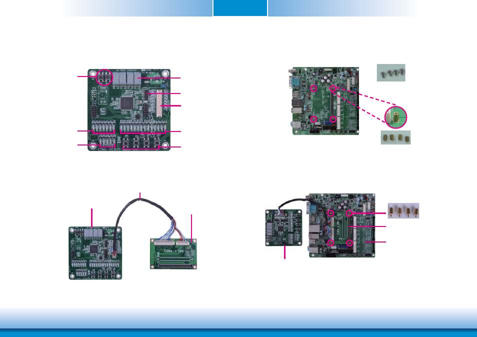
2. Connect the COMe-DEBUG card to COMe-LINK2 via a cable.
COMe-DEBUG
COMe-LINK1/2
Connector
80 Port Display
LPC
COM Express
Signal Display
Power/Reset/
Sleep/LID control
COM Express
Type Display
Code Review
Control
COM Express
Power Display
COMe-DEBUG
COMe-LINK2
Cable
3. Fasten bolts with mounting screws through mounting holes to be fixed in place.
4. Use the provided bolts to fix the COMe-LINK2 debug card onto the carrier board.
Bolts
Mounting screws
Carrier Board
COMe-DEBUG
COMe-LINK2
Bolts
Advertising