Chapter 2 – DFI COM101-BAT User Manual
Page 22
www.dfi .com
Chapter 2 Hardware Installation
22
Chapter 2
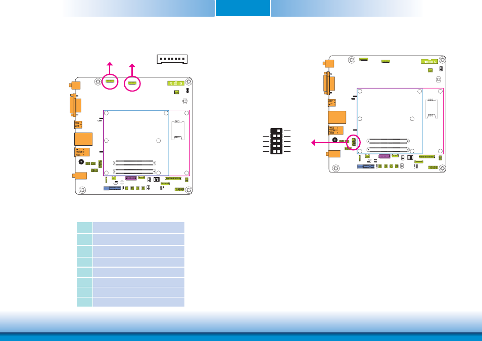
The smart battery charger connectors are used for the function of power mamgement and
determine the accurate battery capacity in the system operation. The function of each pin is
listed below:
Smart Battery Charger Connectors
Smart Battery
Charger 1
Pins
Function
1
V+
2
V+
3
Thermal
4
SMBus_DATA
5
SMBus_CLK
6
V- (GND)
7
V- (GND)
Smart Battery
Charger 2
1
7
LPC connector
The Low Pin Count Interface was defined by Intel
®
Corporation to facilitate the industry’s tran-
sition towards legacy free systems. It allows the integration of low-bandwidth legacy I/O com-
ponents within the system, which are typically provided by a Super I/O controller. Furthermore,
it can be used to interface firmware hubs, Trusted Platform Module (TPM) devices and embed-
ded controller solutions. Data transfer on the LPC bus is implemented over a 4 bit serialized
data interface, which uses a 33MHz LPC bus clock. For more information about LPC bus refer
to the Intel
®
Low Pin Count Interface Specification Revision 1.1’.
LPC
CLK
10
2
9
1
LAD1
RST#
LAD0
FRAME#
VCC3
LAD3
GND
LAD2