Furnace control center, Typical furnace control logic, Furnace control center components – Greenheck PVF/PVG Indirect Gas-Fired Heat Modules (474645) User Manual
Page 4
Indirect Gas-Fired Heat Modules
4
®
Each ventilating unit containing a furnace or a pair of
furnaces will have a furnace control center located on
the furnace vest plate. The control center receives high
voltage AC from the main unit control center and in
most cases, also receives low voltage control signals
(call for heat) from the main unit control center. In all
cases, see the unit-specific wiring schematic located
inside the main control center door.
1. Microprocessor (if present) senses low temperature
on temperature sensor, sends 10 VDC signal to
signal input converter.
2. Input converter changes analog signal to a form that
can be read by the FX controller and sends the signal
to the FX controller (call for heat).
3. FX controller receives call for heat, activates
modulating valve and the ignition controller.
4. Ignition controller receives call for heat from FX
controller, sends spark to igniter and activates the
combination valve. It looks for verification that the
combustion blower is running.
5. Flame sensor detects flame and ignition controller
shuts off igniter.
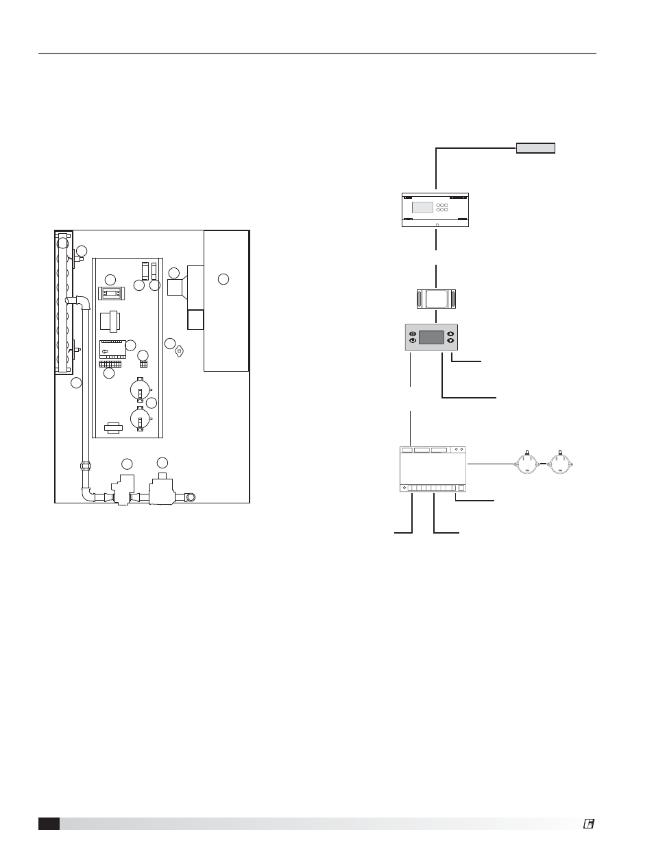
Typical Furnace Control Logic
In all cases, refer to the unit-specific wiring diagram
located on the unit control center door.
This illustration is only for a typical 4:1 turndown
electronic modulation configuration
Temperature Sensor
If there is no DDC, the sensor
is connected to the FX.
DDC
Located in
unit main
control center
FX Controller
Input Converter
Ignition
Controller
Call for heat
Activates and modulates
Modulating Valve
Activates
Ignition Controller
Activates
Combustion Blower
Spark to Igniter
Activates
Combination Valve
JOHNSON
CONTROLS
Controls Speed
of Combustion
Blower
(optional)
(optional)
Furnace Control Center Components
(Components and their locations will vary.)
Components shown are for a typical 4:1 turndown
electronic modulation configuration.
High Voltage Side
1. Power Distribution Block
2. Inducer Relay (controls combustion fan)
3. Combustion Blower
Low Voltage Side
4. Input Converter
5.
FX Controller (modulates heat and switches entire
unit on/off
6. Spark Generator (also has high voltage present)
6a. Spark Igniter
7. 24 volt Terminal Strip
Control Sensors
8. High Temperature Sensor (auto reset)
9. Airflow Switches
10. Flame Sensor
Gas Train
11. Combination Valve
12. Modulating Valve
13. Burner Manifold
14. Collector Box
14
1
2
3
4
5
6
6a
7
8
9
10
11
12
13
Furnace Control Center