Establishing the power supply, Insert the supplied power cable – Guntermann & Drunck LwLVision-USB 2.0 User Manual
Page 11
Installation
G&D LwLVision-USB 2.0 · 8
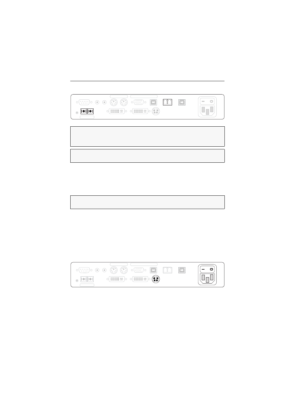
Establishing the data transmission to the user module
Trans. Tx:
Insert the SC plug of a fibre optic cable.
Connect the other end of the cable to the Trans. Rx interface of the user module.
Trans. Rx:
Insert the SC plug of a fibre optic cable.
Connect the other end of the cable to the Trans. Tx interface of the user module..
USB 2.0 Trans. Tx:
Insert the LC plug of a fibre optic cable.
Connect the other end of the cable to the USB 2.0 Trans. Rx interface of the
user module.
USB 2.0 Trans. Rx:
Insert the LC plug of a fibre optic cable.
Connect the other end of the cable to the USB 2.0 Trans. Tx interface of the
user module.
Establishing the power supply
Main Power:
Insert the supplied power cable.
Red. Power:
Use this interface to connect an optional external power pack for a sec-
ond, redundant power supply.
IMPORTANT:
The device uses laser technology complying with laser class 1. Although
class 1 laser beams are considered nonhazardous, avoid direct eye contact.
Do not stare into the beam using optical instruments.
NOTE:
Please remove the protection caps from the Transmission interface and the
cable plugs.
NOTE:
Please remove the protection caps from the USB 2.0 Trans. and the cable
plugs.
Main
Power
RS 232
Red. Power
DVI/VGA Out
DVI/VGA CPU
Line In Line Out
USB 2.0 CPU
Service
Mouse
Keyb.
PS/2
PS/2
USB
Keyb./Mouse CPU
USB 2.0 Trans.
Tx
Rx
Trans.
Tx
Rx
USB 2.0 Trans.
Tx
Rx
RS 232
DVI/VGA Out
DVI/VGA CPU
Line In Line Out
USB 2.0 CPU
Service
Mouse
Keyb.
PS/2
PS/2
USB
Keyb./Mouse CPU
Trans.
Tx
Rx
Main
Power
Red. Power