Herrtronic, Model 6000 – Herrmidifier Herrtronic 6000 Series User Manual
Page 12
Herrtronic
®
Model 6000
I n s t a l l a t i o n , O p e r a t i o n , & M a i n t e n a n c e M a n u a l
12
www.herrmidifier-hvac.com
Maintenance
To maintain output, the water level in the cylinder will slowly
move upwards, exposing new electrode to the water as the
electrodes become coated with minerals. Eventually, all of the
usable electrode surfaces will be coated and the cylinder will be
full of water. At this point, the output will begin to drop and the
red “service” light will come on. The unit will shutdown. This indi-
cates the need to change the cylinder, typically 500-2000 hours
of operation, depending on the quality of the fill water supply.
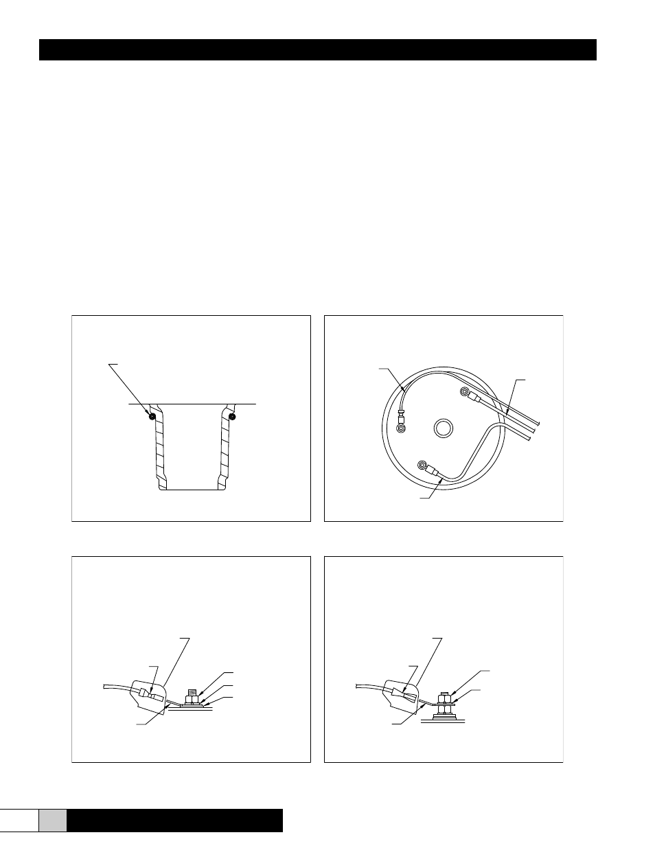
To replace the cylinder
1. Drain cylinder completely using the ‘on-off- drain” switch.
2. Turn off power to the unit at the external disconnect. Dis-
connect electrode power wires (#38 & #39) and cylinder full
electrode wire (#29) from the tank. These connections are
1/4” quick connects. (See Figure 11B, 11C, & 11D)
3. Disconnect 1” hose at top of tank.
4. Remove tank, clean out the drain cup and insert the
Figure 11A
Figure 11C
new tank. Be sure that “o” ring is in place on the cylinder fill/
drain port prior to installation (See Figure 11A). New o-ring
is included with each replacement cylinder.
5. Clean and check both the fill and drain valves while servic-
ing the unit.
6. Check the strainer. If it is dirty or restricting the water-re-
place it.
7. Install cylinder in unit by pushing downward with a slight
twisting motion, while ensuring proper orientation of tank
within cabinet.
8. Reconnect electrode power wires (#38 & #39) and cylinder
full electrode, wire (#29). Make sure that all electrical con-
nections are securely tightened. (See Figure 11B, 11C, &
11D)
9. Follow cold start-up instructions on page 10. Monitor amp
draw for several cycles. .
Extended Shutdown
Always drain cylinder completely if unit will be off for an extend-
ed period of time. This will preserve the life of the cylinder.
Figure 11B
Figure 11D
CYLINDER FILL/DRAIN PORT
POWER WIRE CONNECTIONS
ELECTRODE CONNECTION
CYLINDER FULL ELECTRODE CONNECTION
PROTECTIVE BOOT
(SHOWN TRANSPARENT FOR CLARITY)
(SHOWN TRANSPARENT FOR CLARITY)
PROTECTIVE BOOT
GROMMET
1/4" LOCK WASHER
RED POWER WIRE
1/4"-20 NUT
1/4"-20 NUT
BLACK POWER WIRE
1/4" LOCK WASHER
EST-1060-3
O-RING
1/4" MALE
QUICK CONNECT
1/4" MALE
QUICK CONNECT
CYLINDER FULL
ELECTRODE
WIRE #29
POWER
WIRE #39
POWER
WIRE #38