Herrtronic, Model 6000 – Herrmidifier Herrtronic 6000 Series User Manual
Page 13
Herrtronic
®
Model 6000
I n s t a l l a t i o n , O p e r a t i o n , & M a i n t e n a n c e M a n u a l
13
www.herrmidifier-hvac.com
SECTION V TROUBLESHOOTING GUIDE
All Herrmidifier 6000 Series Humidifiers are manufactured under
strict quality control and are subjected to a complete operational
test before shipment. All circuit board adjustments are made at
the factory and should not be adjusted beyond the guidelines
set in this troubleshooting guide without first consulting a fac-
tory representative. The following information is for your help
and reference. If you still experience difficulty after trying these
remedies, contact your Herrmidifier representative.
WARNING!
The Herrmidifier 6000 Series Electronic Steam Humidi-
fier cabinet was designed to house and shield the com-
ponents from outside interference. Absolutely NO other
components may be mounted inside or be electrically
tapped into the humidifier without Herrmidifier’s express
written permission. Failure to heed this warning will void
your warranty.
TEST POINTS
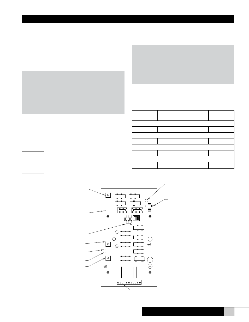
Each circuit board (See Figure 12) features three test points to
aid in the troubleshooting process. Each of these test points
works on a 0-4 VDC scale. “0 VDC” = 0%. “4 VDC” = 100%. All
readings are between the test point and ground (Molex J1, ter-
minal 11 [far right of molex connector, wire #11).
Test Point #1:
Provides exact reading of drain threshold setting.
Test Point #2:
Provides circuit board reference voltage. Should always
read 4 VDC +/-2%.
Test Point #3:
Provides actual percentage of output. For example, a unit
running at 80% of maximum output would have a Test Point
#3 to ground reading of 3.2 VDC.
Maximum Capacity Setpoint
The potentiometer labeled “R39” located in the top left-hand cor-
ner of the board allows adjustment of the unit’s capacity in the
range of 50-100% of maximum.
NOTE:
All blower units have their capacity set from the factory
at 4 lbs/hr. These units can have their capacity increased
by increasing the capacity adjustment potentiometer. En-
sure there is sufficient air circulation in the conditioned
space to prevent condensation on walls or ceiling when
increasing the capacity above 4 lbs/hr.
Circuit Board Settings
Models
Time Cycle
R23
Low Drain
Setting, R18
Capacity,
R39
Standard Settings
All
60 sec
90
100%
High Conductivity Settings (> 1000 micromho)
All
84 sec
93
90%
Softened Water Settings (750-1000 micromho)
All
60 sec
92
95%
Low Conductivity Settings (<100 micromho)
All
60 sec
85
100%
TP3
TP1
TP2
CAP
ADJ
R18
%
R23
SEC
PROP
DISPLAY
CR17
CR18
J1
R4
copyright 1986 HERRMIDIFIER CO, INC.
Test point #2
(Equilibrium voltage reading)
Test point #1
(Drain threshold reading)
Capacity adjustment pot
CR17 LED - overamp
condition indicator if
illuminated
CR18 diode drain
tempering socket
J1 Connector
Cycle timer pot
Low drain
threshold pot
R4 Capacity
resistor socket
(Output capacity)
Test point #3
Figure 12