Back view, Herrtronic, Model 6000 – Herrmidifier Herrtronic 6000 Series User Manual
Page 7
Herrtronic
®
Model 6000
I n s t a l l a t i o n , O p e r a t i o n , & M a i n t e n a n c e M a n u a l
7
www.herrmidifier-hvac.com
SECTION III INSTALLATION INSTRUCTIONS
Mounting
The cabinet is designed to safely contain the working compo-
nents of the Herrmidifier 6000 series humidifier and dissipate
heat to protect the electronics. Locate humidifier, steam pipe
and accessories in a manner to allow routine inspection and any
necessary maintenance. DO NOT install the unit above false
ceilings or around valuable property, where a malfunction could
cause damage. Correct positioning of the humidifier is important
to allow for proper operation and easy maintenance. Minimum
clearance around the cabinet should be maintained as follows:
Minimum Clearances
Around Cabinet
Left
6”
Right
12”
Top
18”
Bottom
12”
Remove foam packing from top of tank.
Four lag bolts, (2) 5/16” and (2) 1/4”, are supplied with the 6000
unit. Install the top two lag bolts (5/16”) according to the dimen-
sions in Figure 3. Hang the unit on the wall, and then install the
bottom two lag bolts (1/4”) and secure all four bolts. Be sure the
unit is level and mounted directly to the wall to wood studs at
least 2” thick (or equivalent). Operating weights are as follows:
6000-1,2: 35 lbs.
6000-3,4: 35 lbs
Figure 3
WARNING!
Do not mount any controls inside the unit or tap power
from any location in the unit, except as stated in these
instructions. Do not place objects near the cabinet. Do
not attach to dry wall without studs. At least one 5/16”
and one 1/4” lag bolt must be located on a stud.
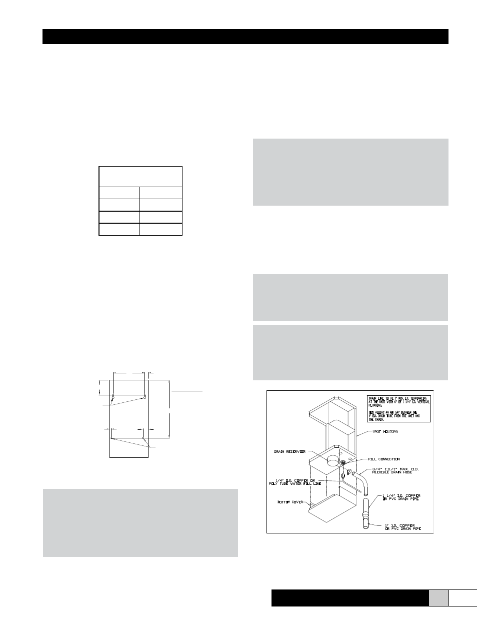
Plumbing
To make the necessary connections for water fill and drain, the
following steps are required: (refer to figure 4 for locations)
1. Install external shutoff valve between the water supply and
the humidifier for ease in servicing the unit.
2. Connect water supply to the 1/4’ compression fitting on the
bottom of the cabinet.
CAUTION!
Do not use reverse osmosis or demineralized water treat-
ment without first consulting the factory. This water may
not be sufficiently conductive to allow proper operation.
Consult factory if water is outside the range of allowable
conductivities. Do not use hot water.
3. Connect the 3/4” tube from the accessory pack to the drain
reservoir. Cut the tube to the length necessary to reach the
drain.
4. Insert the other end of the tube into a minimum 6” vertical
length of the 1-1/4” minimum I.D. drain line. The balance of
the drain line should be 1” I.D. minimum with a minimum
1/8” per foot slope. (See Figure 4)
WARNING!
If the drain line is exposed, it is recommended that it be
insulated for safety. Do not use PVC drain line unless
“Drain Tempering” is enabled (see page 10, step 10).
NOTE:
Inlet water pressure must be in the range of 20-100 psig.
Consult the factory if you are outside this range. Soft-
ened water may be used but requires that the low drain
threshold be adjusted (page 13). Drain water can be tem-
pered to lower its temperature (refer to page 10).
Figure 4
9"
1"
4 1/4"
16 1/2"
1/2"
1 1/2"
5/16 x 5/8 DIA.
KEYHOLE
MOUNTING SLOT
5/16" DIA.
Back View
DRAIN LINE TO BE 1" MIN. I.D. TERMINATING
AT THE UNIT WITH 6" OF 1 1/4" I.D. VERTICAL
PLUMBING.
THIS ALLOWS AN AIR GAP BETWEEN THE
1" O.D. DRAIN TUBE FROM THE UNIT AND
THE DRAIN.
UNIT HOUSING
BOTTOM COVER
FILL CONNECTION
3/4" I.D./1" MAX. O.D.
FLEXIBLE DRAIN HOSE
1/4" O.D. COPPER OR
POLY TUBE WATER FILL LINE
DRAIN RESERVOIR
1 1/4" I.D. COPPER
OR PVC DRAIN PIPE
1" I.D. COPPER
OR PVC DRAIN PIPE