Herrmidifier Herrtronic 6000 Series User Manual
Page 6
Herrtronic
®
Model 6000
I n s t a l l a t i o n , O p e r a t i o n , & M a i n t e n a n c e M a n u a l
6
www.herrmidifier-hvac.com
Engineering and Application
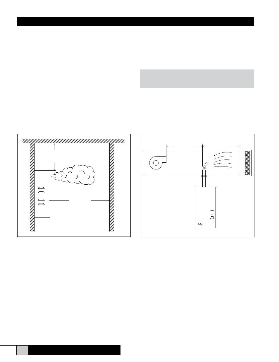
The Herrmidifier 6000 Series Steam Humidifiers can be applied
in a variety of applications. The simplest application is to utilize
the model with the built-in blower package (6000-1,2). The
steam generated by the unit is distributed into the conditioned
space by the built-in blower package (Figure 1).
Alternatively, steam generated by the “6000” unit can be dis-
charged directly into the HVAC system ductwork (6000--3,4).
In this application, a steam pipe is preferably installed in the
system ductwork at least 5 feet downstream of the supply air
blower. There should be no obstructions within the first 5 feet
downstream of the steam distributor as shown in Figure 2. An
air proving switch and high limit humidistat are provided for bet-
ter system control in ducted applications. If the heating system
Figure 1
Allowable Operating Conditions:
Ambient Temperature: 40°F (4°C) to 120°F (50°C)
Ambient Relative Humidity: 0% to 90% (non-condensing)
Line Voltage: -15% to +10% of Nominal
Frequency: 50/60 HZ.
Water Supply Pressure: 20psi – 100 psi.
Maximum Duct Static Pressure: 1” (6000-4)
operates for short periods at a time and the desired relative
humidity level is not achieved, the humidifier can be wired to
turn on the blower when there is a call for humidity. In this case
an air proving switch will not be necessary, but the high limit
humidistat should still be utilized.
NOTE:
The steam distributor pipe is inherently sloped to return
the condensate to the humidifier.
The steam piping from the humidifier to the steam distribu-
tor should have an 8% slope (1” per foot) up to the steam
distributor. Steam hose may be used up to a maximum of 20
feet between the unit and the steam distributor. The hose
provided with the unit is 10 feet long. There can be no sags in
the steam hose, as this will create a trap and will produce back
pressure in the steam cylinder and may blow condensate in the
duct.
Figure 2
Note: Duct liner may be used
with a maximum
thickness of 1".
5 FEET MINIMUM
5 FEET MINIMUM
18 INCHES
MINIMUM
5 FEET MINIMUM