ILS ILS22G winXP User Manual
Page 8
6
RPT2, the stereo jack is issuing a +\or – 5 volt to switch the 2-way VGA switcher inside the ILS24G version with the
cabinet that includes a 4-way and a 2-way Extron switcher (but may also be used for other purposes)
The RPT3 RJ45 has 4 circuits on its 8 connectors that are opened
or closed by the relays for any need.
Do not apply more than 12 volts per pin pair!
The remaining 2 relays are for internal use (microphone mute
switch and optional light switch)
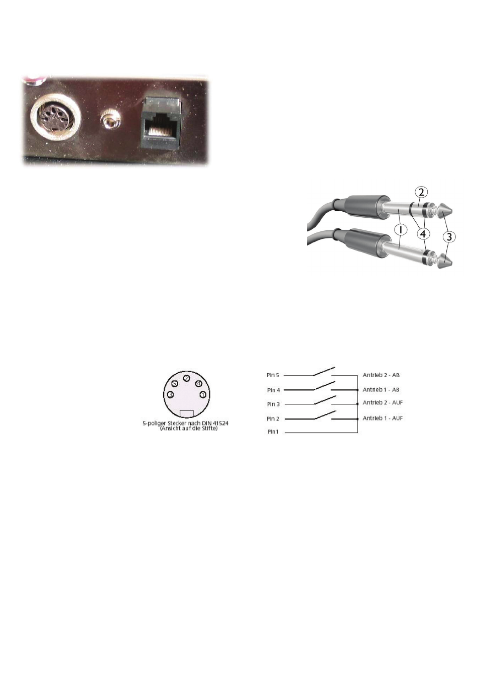
Socket layouts:
1. Sleeve: usually ground
2. Ring: Right-hand channel for stereo signals, negative phase for balanced
mono signals, power supply for power-requiring mono signal sources
3. Tip: Left-hand channel for stereo signals, positive phase for balanced
mono signals, signal line for unbalanced mono
signals
4. Insulating rings
3,5 mm jack plug stereo
relay no:
field protocol:
1= white wire = ground
2= brown wire = ring
3,4
24 & 25
3= green wire = tip
DIN plug 5 pins:
1= gray wire
2= yellow wire
1,2
22 & 23
4= pink wire
RJ 45 connector:
1= orange/white wire
2= orange wire
3= green/white wire
4= blue wire
6,7,8,9
27,28,29,30
5= blue/white wire
6= green wire
7= brown/white wire
8= brown wire