ILS ILS22G winXP User Manual
Page 9
7
XLR5:
relay no:
field protocol:
1= ground(shield)
2= switch ------------------- blue wire
5
26
3= negative signal-------------blue wire
4= switch --------------------white wire
5
26
5= positive signal--------------white wire
XLR3:
1= ground(shield)
2= positive signal-------------white wire
3= negative signal------------blue wire
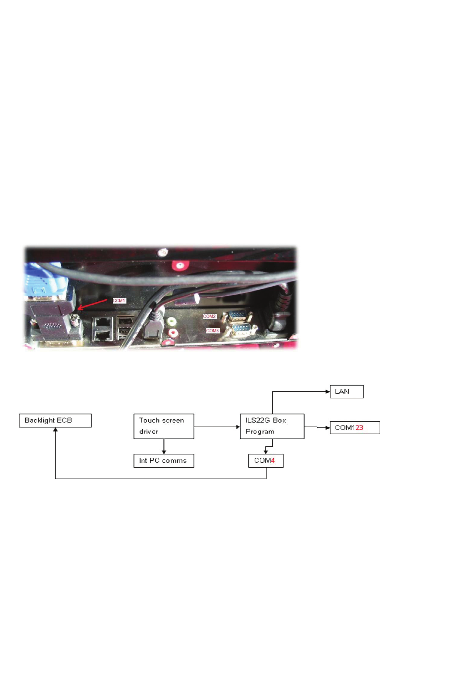
Note: Reserve on connector P4 are relay numbers 10 &11 with respectively field protocols 31 and 32. Pin numbers P4 are 17,18
(relay number 10); 19, 20 (relay number 11). All commands are issued through the COM4 port.
COM1, COM2 and COM3 are available to hook up RS232 controllable devices, such as projectors or the 4-way
switcher inside the ILS24G 19”cabinet based version.
Next to the LAN network connector, the second LAN port can be used to connect to IP protocol driven control systems.
The flexibility in addressing and programming is endless.
However in our implementation we regarded mainly what functions are needed when one is standing behind the lectern.
eg. ‘Projector on’ may trigger the projector to start, but you could also combine that with issuing commands to close the
curtains, lower the screen and dim the lights.
Similarly the lights button is for having the lights up or dimmed, no matter how many bays of light switches are behind
that. We do not claim to control every possible light setting. If that is required, use the “Extra Buttons”-button to open
a room control application on the PC screen and use that to adjust the settings. This also applies if you require a local
language keyboard; just program that link to an OSK under the “Extra Buttons”-button.
Depending customer requests ILS may program more keys and function keys under the extra buttons.