0 measurement techniques, 1 circuit – Interlink Electronics FSR 400 Series User Manual
Page 23
www.interlinkelectronics.com
21
FSR
®
Integration Guide
6.0 Measurement
Techniques
6.1 Circuit
Voltage Divider
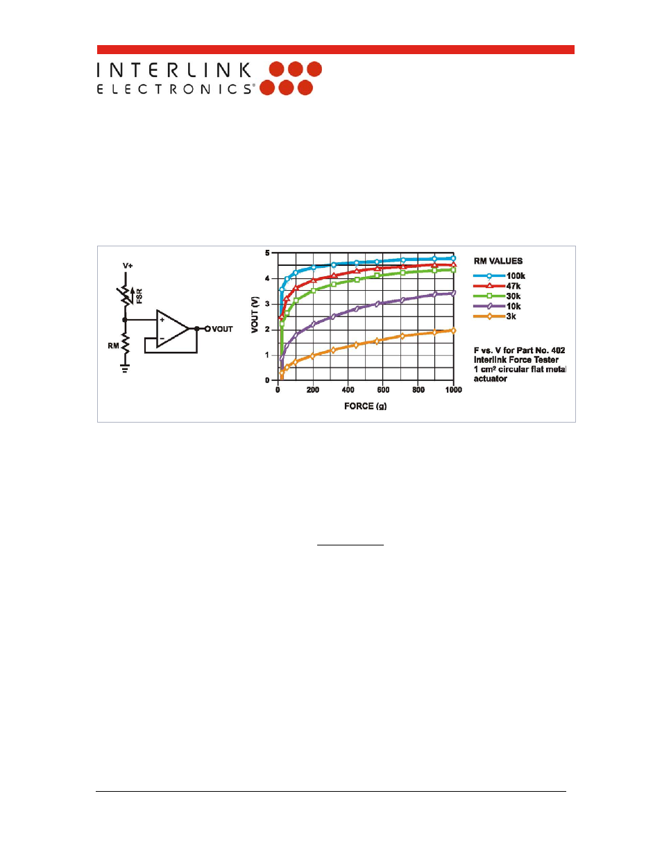
Figure 10: FSR Voltage Divider
FSR Voltage Divider
For a simple force-to-voltage conversion, the FSR device is tied to a measuring resistor
in a voltage divider (see figure below) and the output is described by the following
equation:
FSR
M
M
OUT
R
R
V
R
V
In the shown configuration, the output voltage increases with increasing force. If R
FSR
and
R
M
are swapped, the output swing will decrease with increasing force.
The measuring resistor, R
M
, is chosen to maximize the desired force sensitivity range and
to limit current. Depending on the impedance requirements of the measuring circuit, the
voltage divider could be followed by an op-amp
A family of Force vs. V
OUT
curves is shown on the graph above for a standard FSR in a
voltage divider configuration with various R
M
resistors. A (V+) of +5V was used for these
examples. Please note that the graph values are for reference only and will vary
between different sensors and applications.