Interlink Electronics FSR 400 Series User Manual
Page 29
www.interlinkelectronics.com
27
FSR
®
Integration Guide
The output swing of this circuit is from (VREF/2) to VREF. In the case where RG is
greater than RFSR, the output will go into positive saturation.
For either of these configurations, a zener diode placed in parallel with RG will limit the
voltage built up across RG. These designs yield one-half the output swing of the previous
circuit, but only require single sided supplies and positive reference voltages. Like the
preceding circuit, the current through the FSR should be limited to less than 1 mA/square
cm of applied force.
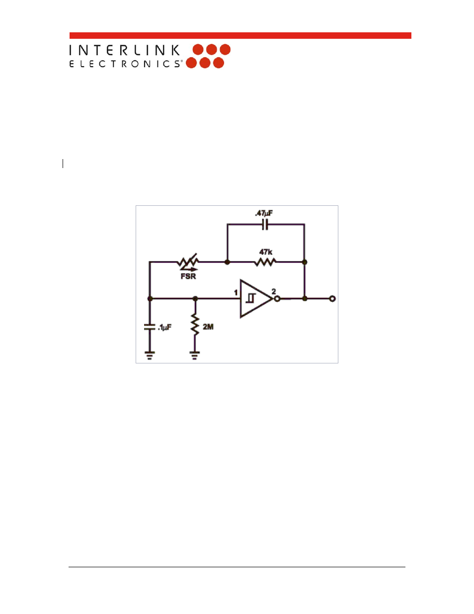
FSR Schmitt Trigger Oscillator
Figure 17: FSR Schmitt Trigger Oscillator
In this circuit, an oscillator is made using the FSR device as the feedback element around
a Schmitt Trigger. In this manner, a simple force-to-frequency converter is made. At zero
force, the FSR is an open circuit. Depending on the last stage of the trigger, the output
remains constant, either high or low. When the FSR is pressed, the oscillator starts, its
frequency increasing with increasing force. The 2MΩ resistor at the input of the trigger
insures that the oscillator is off when FSRs with non-infinite resistance at zero force are
used. The 47kΩ resistor and the 0.47 µF capacitor control the force-to-frequency
characteristic. Changes in the “feel” of this circuit can be made by adjusting these values.
The 0.1µF capacitor controls the frequency range of the oscillator. By implementing this
circuit with CMOS or TTL, a digital process can be controlled by counting leading and/or
trailing edges of the oscillator output. Suggested Schmitt Triggers are CD40106,
CD4584 or 74C14.