Interlink Electronics FSR 400 Series User Manual
Page 27
www.interlinkelectronics.com
25
FSR
®
Integration Guide
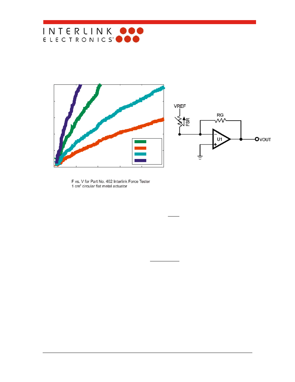
0
200
400
600
800
1000
0
1
2
3
4
5
FORCE (g)
V
O
UT
(V
)
7.5 k
4.7 k
2.5 k
1.5 k
FSR Current-to-Voltage Converter
In this circuit, the FSR device is the input of a current-to-voltage converter. The output of
this amplifier is described by the equation:
FSR
G
REF
OUT
R
R
V
V
With a positive reference voltage, the output of the op-amp must be able to swing below
ground, from 0V to –VREF, therefore dual sided supplies are necessary. A negative
reference voltage will yield a positive output swing, from 0V to +VREF.
FSR
REF
G
OUT
R
V
R
V
VOUT is inversely proportional to RFSR. Changing RG and/or VREF changes the
response slope. The following is an example of the sequence used for choosing the
component values and output swing:
For a human-to-machine variable control device, like a joystick, the maximum force
applied to the FSR is about 1kg. Testing of an example FSR shows that the
corresponding RFSR at 1kg is about 2.9kΩ. If VREF is – 5V, and an output swing of 0V
to +5V is desired, then RG should be approximately equal to this minimum RFSR. A full
swing of 0V to +5V is thus achieved. A set of FORCE vs. VOUT curves is shown in
Figure 15 for a standard FSR using this interface with a variety of RG values.
Figure 14: FSR Current-to-Voltage