Interlink Electronics FSR 400 Series User Manual
Page 28
www.interlinkelectronics.com
26
FSR
®
Integration Guide
The current through the FSR device should be limited to less than 1 mA/square cm of
applied force. As with the voltage divider circuit, adding a resistor in parallel with RFSR
will give a definite rest voltage, which is essentially a zero-force intercept value. This can
be useful when resolution at low forces is desired.
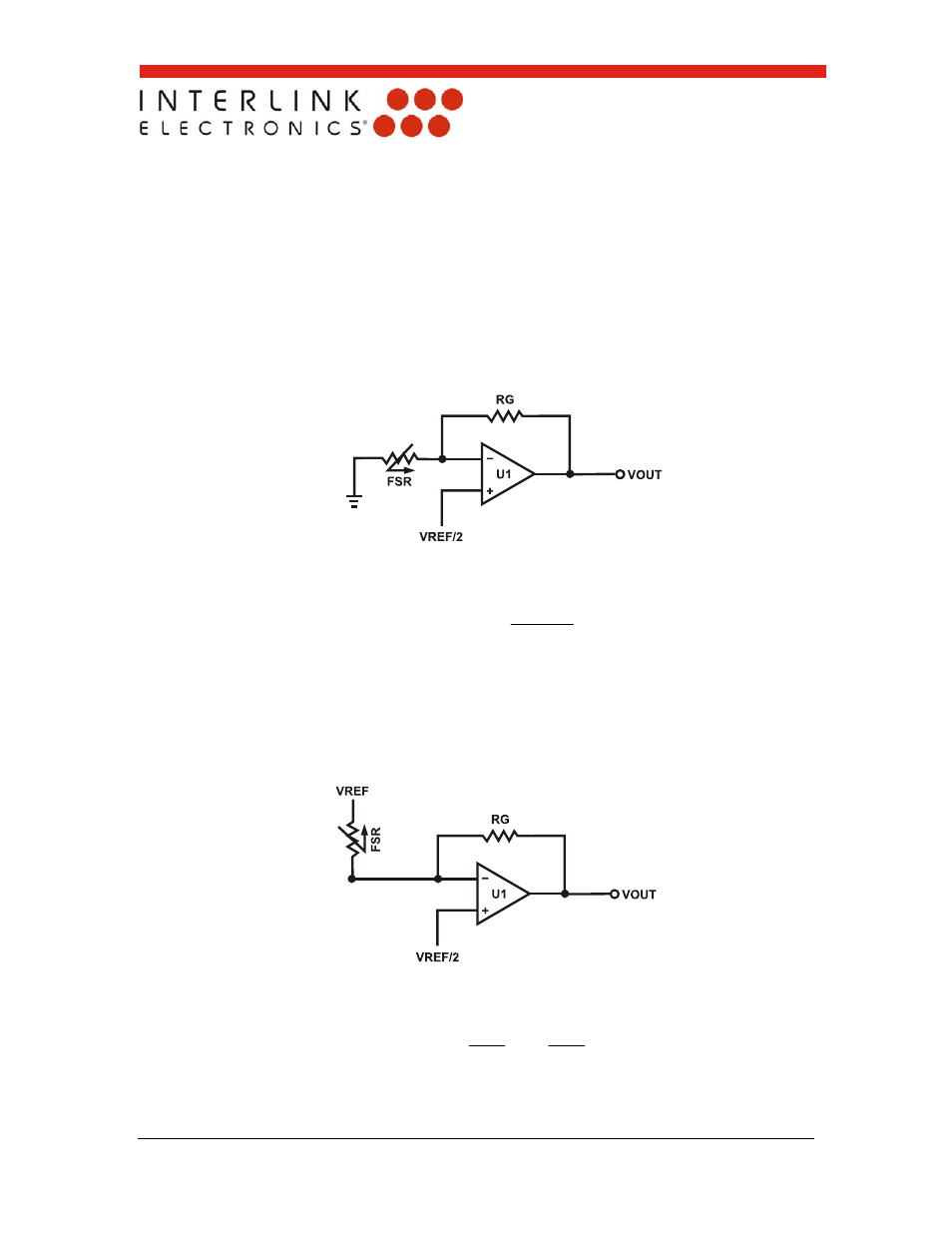
Additional FSR Current-to-Voltage Converters
These circuits are a slightly modified version of the current-to-voltage converter detailed
on the previous page. Please refer to it for more detail.
Figure 15: Additional FSR Current-to-Voltage Converter
The output of Figure 15 is described by the equation:
V
V
V
R
V
out
M
OUT
The output swing of this circuit is from (VREF/2) to 0V. In the case where RG is greater
than RFSR, the output will go into negative saturation.
Suggested op-amps are LM358
and LM324.
Figure 16: Additional FSR Current-to-Voltage Converter
The output of Figure 16 is described by the equation:
FSR
G
REF
OUT
R
R
V
V
1
2