Connections, controls, and indicators – LD Systems ZONE 624 User Manual
Page 6
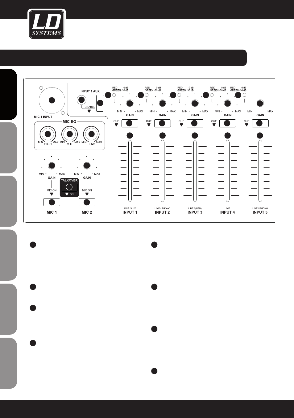
connectionS,
ConTRoLS, AnD InDICAToRS:
1
MIC 1 / 2 on
On/Off switch for the microphone channels 1 and
2 with built-in red LED. When button is pressed,
the microphone channel is switched on and the
LED light turns on.
2
GAIn MIC 1 / 2
Volume control for the microphone inputs 1 and 2.
3
InPUT MIC 1
Balanced microphone input MIC 1 with XLR /
6.3 mm jack (combo). The microphone input is
equipped with a 12 V phantom power.
4
eQ HIGH MIC 1 / 2
Equalizer high band for the microphone channels 1
and 2. When turned to the left, levels are lowered,
when turned to the right, they are raised. In the centre
position (resting point), the equalizer is inactive.
5
eQ MID MIC 1 / 2
Equalizer mid band for the microphone channels 1
and 2. When turned to the left, levels are lowered,
when turned to the right, they are raised. In the centre
position (resting point), the equalizer is inactive.
6
eQ LoW MIC 1 / 2
Equalizer low band for microphone channels 1 and
2. When turned to the left, levels are lowered, when
turned to the right, they are raised. In the centre
position (resting point), the equalizer is inactive.
7
TALKoVeR on
Switch with built-in blue LED. When button is pressed,
the talkover feature is switched on and the LED light
turns on. More setting options for the talkover feature
are located on the back panel of the device.
8
AUX In InPUT 1
Stereo line input with 3.5 mm stereo jack.
6
ENGLISH
DEUTSCH
FRANCAIS
FRANCAIS
FRANCAIS
FRANCAIS
FRANCAIS
ES
pA
ño
L
po
LSKI
IT
ALIAN
o
1
1
2
2
3
4
5
6
7
8
9
10
11
12
13
10
11
12
13
10
11
12
13
10
11
12
13
10
11
12
13