Connections, controls, and indicators – LD Systems ZONE 624 User Manual
Page 7
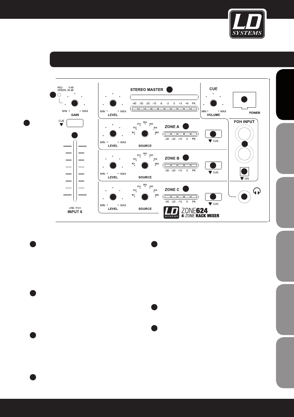
connectionS,
ConTRoLS, AnD InDICAToRS:
9
AUX enABLe InPUT 1
Switch with built-in blue LED to select the input
source for the INPUT 1 channel. If the switch is not
pressed, the LINE input on the back panel is selected
as the signal source. In the pressed position, the AUX
input on the front is selected (LED is on).
10
GAIn InPUT 1 - 6
To harmonise playback devices (CD player, MP3
player etc.) with different output levels, adjust the
input gain of the INPUT channels 1 - 6 with the
help of this GAIN control.
11
SIGnAL LeD InPUT 1 - 6
The signal LED lights up green when an audio
signal is present at the input of the respective
channel. The LED lights up red when the optimum
volume level (0 dB) is reached.
12
VoLUMe InPUT 1 - 6
Volume control for channel INPUT 1 to 6.
13
CUe InPUT 1 - 6
Cue switch with built-in red LED for INPUT
channels 1 - 6. If the switch is pressed (LED is
on), the input signal is routed to the headphone
output on the front panel of the device. The signal
is sourced before the volume control of each
channel, therefore it is independent of the setting
of the volume control.
14
MASTeR LeVeL
Volume control for the MASTER channel.
15
LeVeL MeTeR STeReo MASTeR
Level meter display with 2 x 10 LED segments
(left / right). Once the peak LED (PK) lights up, the
device is operating at the distortion limit. It is not
critical if the LED lights briefly at peak levels for the
incoming signal, however continuous illumination
should be avoided by reducing the volume.
7
IT
ALIANO
POLSKI
ESP
AÑOL
FRANCAIS
FRANCAIS
FRANCAIS
FRANCAIS
FRANCAIS
DEUTSCH
ENGLISH
15
14
16
16
16
17
17
17
18
18
18
19
19
19
20
21
22
23
24
10
11
12
13