Lynx Studio Aurora 16 User Manual
Page 15
Page 13
2.6.2 Aurora as Clock Slave
The Aurora can synchronize to sample clock from a variety of external sources. In order to establish
the Aurora as a clock slave, the correct clock source must be specified and the appropriate physical
connection made. A two-stage phase-lock loop system is used to generate a high-frequency PLL clock
while attenuating jitter in the selected sample clock source. Refer to Section 2.6.3 for a description of
the operation of the PLL’s.
To choose the desired clock source, depress the SYNC SOURCE button on the Aurora front panel
(see Section 2.1 Front Panel Controls and Indicators, item
w
) until the LED for the correct choice
illuminates. With a valid external clock source selected, the incoming clock will be measured by the
Aurora, and the LED that corresponds to measured sample rate in the SAMPLE RATE portion of the
front panel will illuminate (see Section 2.1 Front Panel Controls and Indicators, item
q
). In addition
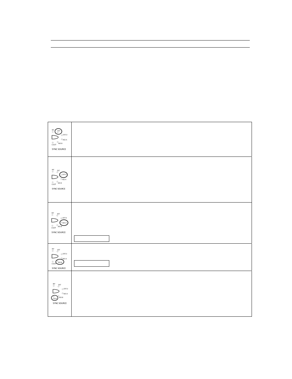
to “INT”, which is described in Section 2.6.1 Aurora as Clock Master, clock choices include:
EXT - External
Clock signals from WORD CLOCK connector (see Section 2.3 Back Panel Connections,
item
2)
). This input supports TTL signal levels and is terminated with 75 ohms of
impedance. Connect this input to the word clock output of an external device using a 75-
ohm cable with BNC connectors. Please note that the Aurora does NOT support 256X
word clock, also known as Super Clock.
EXT/2 - External Divided by 2
Clock signals from the WORD CLOCK connector. In this mode, the word clock signal
received will be reduced by half. As an example, a received clock rate of 96kHz will run at
48kHz. This mode is necessary to operate in dual-wire mode, where each physical input or
output connection passes a single channel of AES/EBU signal running at half the system
sample rate, thereby allowing high sample rate operation with legacy devices that do not
support single-wire operation over 50kHz. For more information on dual-wire operation,
see Section 2.1 Front Panel Controls and Indicators, item
a
AES A – Port A Digital Input
Word Clock recovered from the Port A digital input. All four AES3 inputs on Port A are
scanned, and clock is derived from the first valid AES/EBU channel. If there are no valid
sources connected to Port A, Port B will be scanned for a valid clock source. If multiple
digital devices are connected to this port, connect the device that you intend to be the clock
source to Input 1.
Aurora 8
Wordclock from AES inputs 1-4.
AES B – Port B Digital Input
Word Clock recovered from the Port B digital input, like above. If no valid sources are
connected to Port B, Port A will be scanned for a valid clock source.
Aurora 8
Wordclock from AES inputs 5-8.
LSLOT
Sample clock derived from cards installed in the LSlot expansion port. As an example, if
the LT-ADAT is installed, and the intended clock source was a device connected to the one
of the LT-ADAT’s optical inputs, LSLOT should be selected as the sync source. With
LSlot expansion devices (like the LT-ADAT) that can receive clock from more than one
port or channel, clock from the first valid port or channel will be used as the clock source.
Whenever possible, connect the device intended to provide sample clock to the first
available port and/or channel of the LSlot device.