Lynx Studio LT-MADI User Manual
Page 19
Page 16
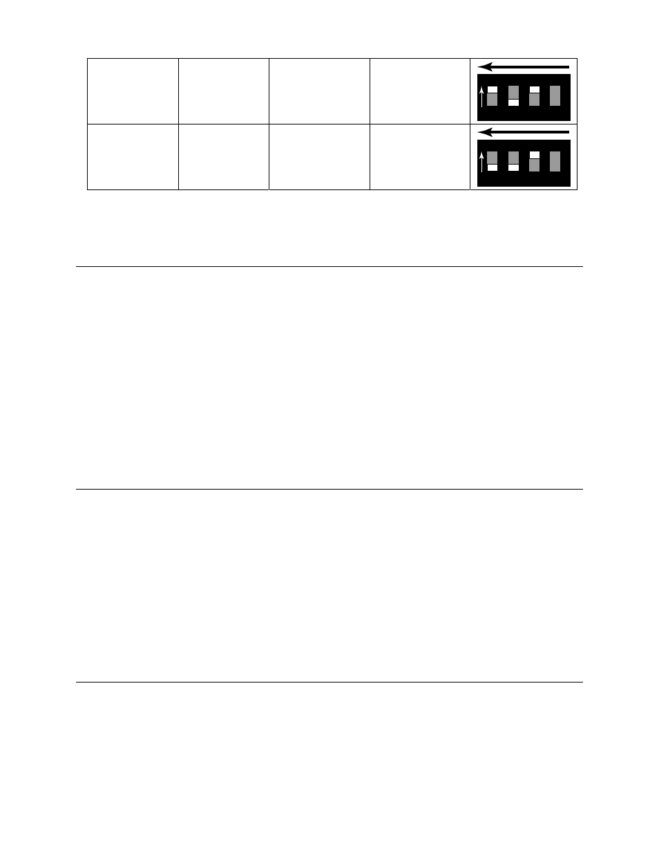
ON OFF ON Device
2
1 2 3 4
ON C&K SDA04
Back of Aurora
OFF OFF ON Device
3
1 2 3 4
ON C&K SDA04
Back of Aurora
The factory default state of these Switches is for Single Aurora operation.
7.4.2 Delay Compensation
Each device in a MADI chain operates a number of samples behind or ahead of the previous
device, due to latencies intrinsic to the transportation of MADI data through the daisy-chain.
Normally, the result of this disparity would be that streams from multi-unit systems would NOT
be sample aligned. The LT-MADI has a mechanism to correct for this disparity. Internal delay
compensation for each unit insures that analog signals are sample aligned, even with four units
connected. The amount of delay compensation that is applied is determined by the Unit ID on
the LT-MADI card. For that reason, it is important that the Auroras are daisy chained consistent
with the Unit ID position (i.e. Device 0 into Device 1 into Device 2 etc.). Delay Compensation,
as stated previously, is turned ON with the SW3 switch and should always be ON for multi-
Aurora systems.
The delay compensation affects all Analog and AES/EBU inputs and outputs, at all sample rates.
7.4.3 Unit Bypass
When all MADI channels are being deployed by Auroras on a chain, additional Auroras are put
in bypass mode (MADI in and out are bypassed). Bypass is relative to the sample rate. If, for
instance, 4 Auroras in 16-channel mode are chained together at 44.1/48 kHz sample rates, I/O
from all 4 units will be utilized. At an 88.2/96 kHz sample rate, only the first two units in the
chain will be utilized and the last two put into Bypass mode. This is because at the 2X sample
rates MADI supports a maximum of 32-channels. LED5 being turned ON (green) indicates that
the LT-MADI card is in bypass mode.
Section 7.4.5 details several common multi-Aurora scenarios and which units are in bypass mode
at different sample rates.
7.4.4 Daisy-Chaining Units
In MADI systems where signal flow is ingoing and outgoing, connected devices typically form a
loop. In systems where audio only travels either upstream or downstream (ie. either recording or
playback, but not both), then creating a complete daisy-chained loop is not necessary.
The graphics below detail some common scenarios to use as a configuration guide.